Digital Air Surveillance Radar (DASR) ASR 11
Description of the radar set, tactical-technical characteristics
| Specifications | |
|---|---|
| frequency: | 2,7 bis 2,9 GHz |
| pulse repetition time (PRT): | |
| pulse repetition frequency (PRF): | |
| pulsewidth (τ): | 1 µs and 80 µs |
| receive time: | |
| dead time: | |
| peak power: | 25 kW |
| average power: | 2.1 Kilowatt |
| instrumented range: | 60 NM |
| range resolution: | 926 m (0.5 NM) |
| accuracy: | |
| beamwidth: | 1.41° |
| hits per scan: | |
| antenna rotation: | 12 RPM |
| MTBCF: | |
| MTTR: | |
Digital Air Surveillance Radar (DASR) ASR 11
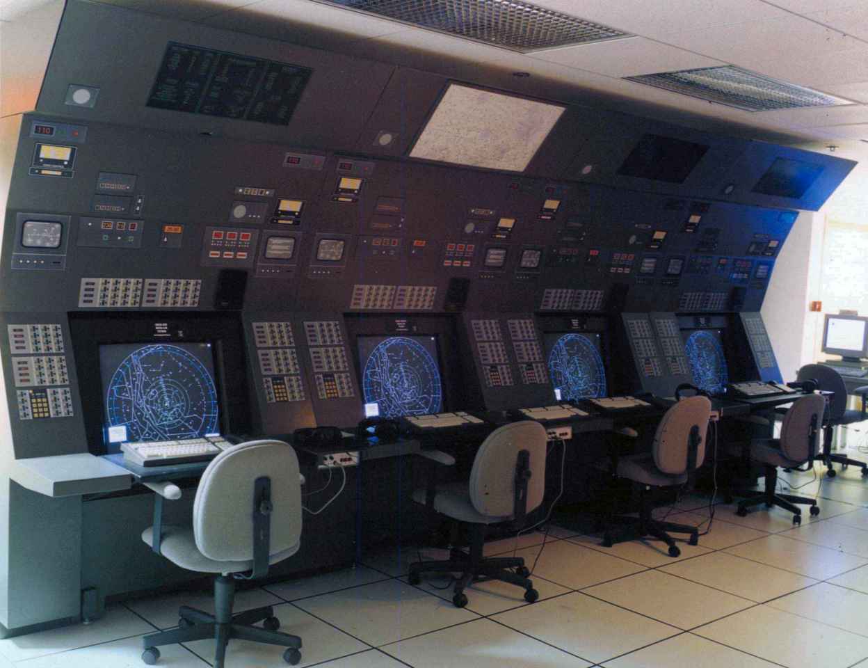
The Digital Airport Surveillance Radar (DASR) (military designator: AN/GPN-30) is a terminal air traffic control radar system that replaces current analog systems with new digital technology. The DASR system detects aircraft position and weather conditions in the vicinity of civilian and military airfields. The Government nomenclature for this radar is the ASR 11. The ASR 11 will replace existing ASR-7, ASR 8 and AN/GPN-12, -20 and -27 systems. These older radars, some up to 20 years old, are being replaced to improve reliability, provide additional weather data, reduce maintenance cost, improve performance, and provide digital data to new digital automation systems for presentation on air traffic controller displays.
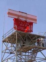
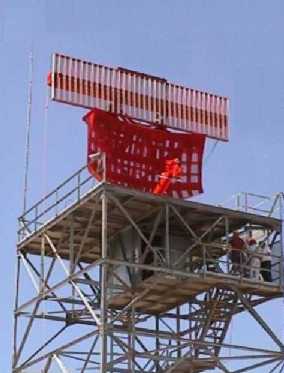
The ASR 11 system consists of two electronic subsystems: a primary surveillance radar and a secondary surveillance radar, sometimes called the beacon. The primary surveillance radar uses a continually rotating antenna mounted on a tower to transmit electromagnetic waves which reflect or backscatter from the surface of aircraft up to 60 miles from the radar. The radar system measures the time required for radar echo to return and the direction of the signal. From this data the system can then measure the distance of the aircraft from the radar antenna and the azimuth or direction of the aircraft from the antenna. The primary radar also provides data on six levels of rainfall intensity. The primary radar operates in the range of 2 700 to 2 900 MHz. The transmitter generates a peak effective power of 25 kW and an average power of 2.1 kW. Average power density of the ASR 11 signal decreases with distance from the antenna. At distances of more than 43 feet from the antenna, the power density of the ASR 11 signal will fall below the maximum permissible exposure levels established by the Federal Communications Commission.
Source: Factsheet www.faa.gov
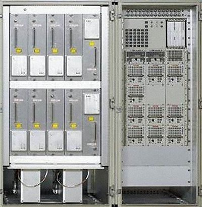
The cabinet on the left-hand part of Figure 2 is the transmitter. The drivers are the two rightmost boxes and the power amplifiers are the two rows of four boxes each, to the left of the drivers. The right-hand part of Figure 2 is the power supply rack. Although it does supply power to the transmitter, it also provides power to the receivers and signal data processors.
