Flycatcher
Description of the radar set, tactical-technical characteristics

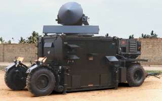
Figure 1: Flycatcher, the cone on top is the tracking antenna, the bar underneath is the search antenna.

Figure 1: Flycatcher, the cone on top is the tracking antenna, the bar underneath is the search antenna.
| Specifications | ||
|---|---|---|
| Search | Tracking | |
| frequency: | 9 200 MHz I-Band |
I-Band or K-Band |
| pulse repetition time (PRT): | ||
| pulse repetition frequency (PRF): | 4 800 Hz | |
| pulsewidth (τ): | 0.2 µs | |
| receive time: | ||
| dead time: | ||
| peak power: | 160 kW | |
| average power: | 160 W | |
| instrumented range: | 20 km | |
| range resolution: | 30 m | |
| accuracy: | ||
| beamwidth: | 1.1° | 2.4° or 4.2° |
| hits per scan: | ||
| antenna rotation: | 40 min-1 | 10 min-1 |
| MTBCF: | ||
| MTTR: | ||
Flycatcher
The Flycatcher is a weapon control radar for air defense fire control system for tanks, guns and missiles. It consists of two radars providing the acquisition and tracking element.
The search antenna is of slotted waveguide type with a length of 5 ft (1.5 m). It is deployed co-axially with the parabolic dish antenna in the Flycatcher system. The tracking radar antenna is situated center/front turret while the search radar antenna is mounted rear/top turret. Both antennas uses its own receiver. The transmitter of the search radar is operating in I-Band and uses a magnetron. In some versions this one transmitter provides also the tracking radar. In other versions the tracking radar uses its own transmitter operating in K-Band.
TV tracking is an integral part of the Flycatcher system. This camera uses an optical zoom of 30 … 300 mm.

