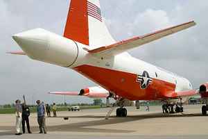
Airborne Radar ELDORA/ASTRAIA
Description of the radar set, tactical-technical characteristics
| Specifications | |
|---|---|
| frequency: | 9.3 – 9.8 GHz ( X-Band) |
| pulse repetition time (PRT): | |
| pulse repetition frequency (PRF): | 2 – 5 kHz |
| pulsewidth (τ): | 0.25 – 3.00 µs |
| receive time: | |
| dead time: | |
| peak power: | 35 – 40 kW |
| average power: | |
| instrumented range: | 20 – 90 km |
| range resolution: | 37.5 – 1200 m |
| accuracy: | |
| beamwidth: | 1.8° |
| hits per scan: | |
| antenna rotation: | |
| MTBCF: | |
| MTTR: | |
Airborne Radar ELDORA/ASTRAIA
The ELDORA (Electra Doppler Radar) / ASTRAIA (Analyse Stereoscopique par Radar Aeroporte Sur Electra) is an X-Band, dual beam, airborne Doppler radar that has been jointly built by the National Center for Atmospheric Research (Boulder, USA, Colorado) and by the French Centre National de Recherche Scientifique (CNRS) in Paris. The ELDORA/ASTRAIA radar is designed to provide high-resolution measurements of the air motion and rainfall characteristics of very large storms, storms that are frequently too large or too remote to be adequately observed by ground-based radars.
The ELDORA/ASTRAIA design features a dual-beam, fore-aft scanning technique permitting the radar (two complete radar systems) to collect dual Doppler information in flight. The scan pattern enables collection of dual fore- and aft-pointing Doppler velocity data, the analysis of this data provides 2-D wind fields on observation surfaces passing through the storm. The instrument makes use of a complex transmitted waveform which consists of 4 different frequencies. In addition the radar transmits a shorter pulse than is needed in the output data sample. These data are averaged in the digital signal processor to provide the required additional samples.
The radar consists of 5 major functional blocks:
- the RF signal generator/receiver unit;
- the high power amplifiers;
- the signal processor;
- the antenna/rotodome system;
- and the radar control equipment.
The two 35 kW peak power traveling wave tube amplifiers are driven by a common synthesizer using a high-precision 10 MHz crystal oscillator as master-oscillator. The synthesizer generates all the needed reference frequencies for the fore and aft radar transmitters. The 60 MHz intermediate frequency (IF) is generated by the RF signal generation hardware and is used by the receivers, the IF signal processors, the master timing module, and the digitizers. The transmitted signal consists of pulses which contain sub-pulses, or chips for each of the four separate transmitted frequencies. The transmitted pulses can be transmitted at staggered intervals in order to assist with range-velocity ambiguity reduction.
The transmitted signal passes through a dual channel rotary joint to separate fore and aft antennas which are mounted in the rotodome. Its two antennas extend back from the tail of the aircraft and spin about the longitudinal axis of the aircraft at a rate of 20 – 40 rpm to provide the required scanning motion.
Source: Herbert J. Kramer: “Observation of the Earth and its Environment: Survey of Missions and Sensors” Berlin, Heidelberg: Springer Berlin Heidelberg, 1994., ISBN 9783662090404 (Presentation of the book)

