Traveling Wave Tube
What is a traveling wave tube?
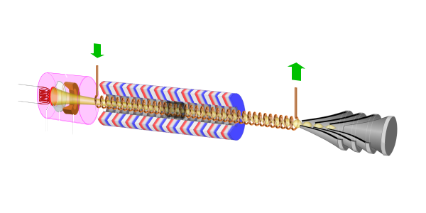
Figure 1: Physical construction of a TWT: ① Electron gun; ② Surrounding magnet; ③ Slow wave structure (here: Helix); ④ Collector;
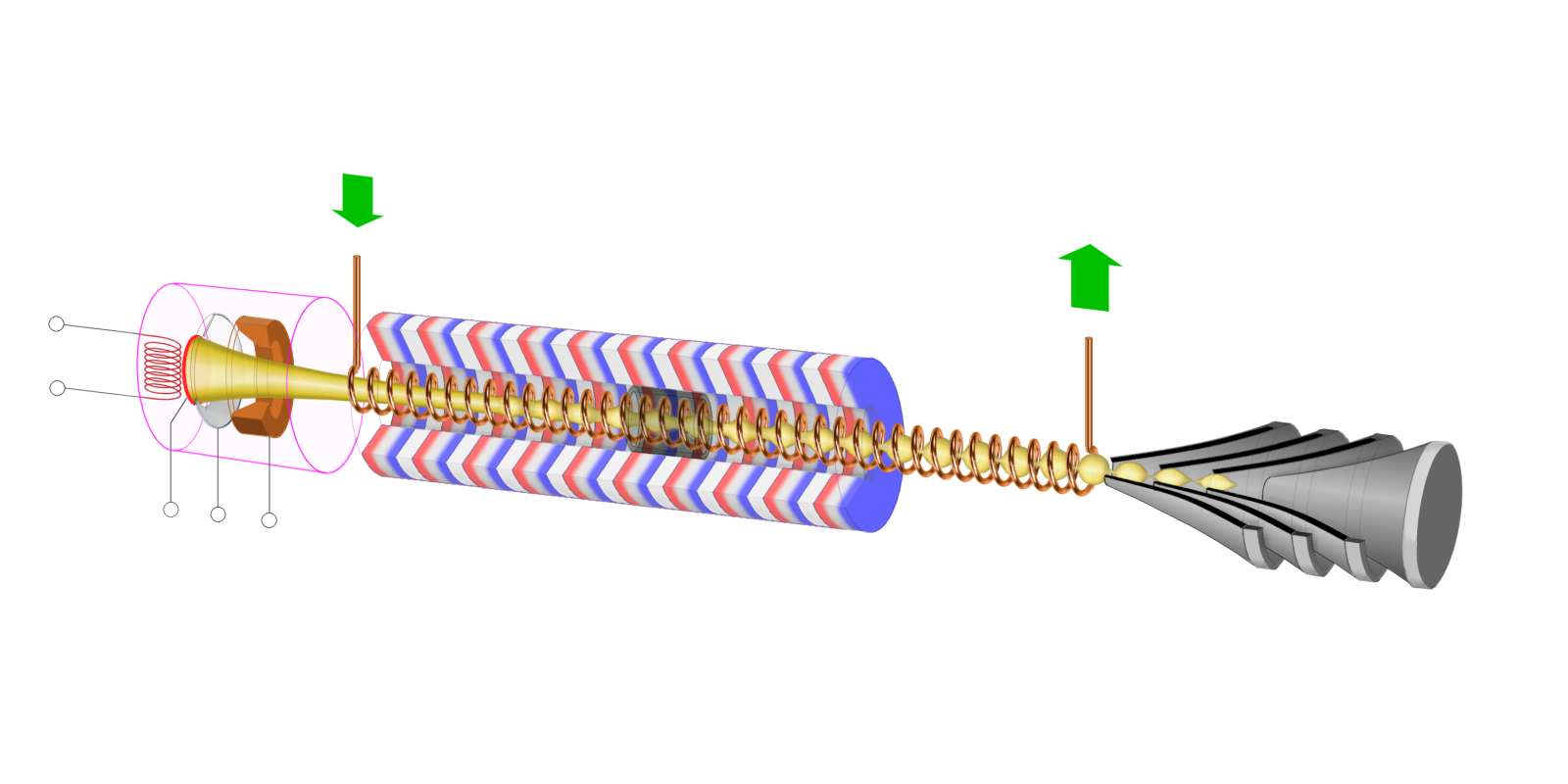
Figure 1: Physical construction of a TWT

Figure 1: Physical construction of a TWT: ① Electron gun; ② Surrounding magnet; ③ Slow wave structure (here: Helix); ④ Collector; (interactive picture)
Traveling Wave Tube
Traveling Wave Tubes (abbr.: TWT, pronounced: “twit”) are vacuum tubes used as high-gain, low-noise, wide-bandwidth microwave wideband amplifiers. A TWT is capable of gains from 40 to 70 dB with bandwidths exceeding two octaves.[1] (A bandwidth of 1 octave is one in which the upper frequency is twice the lower frequency.) TWTs have been designed for frequencies as low as 300 Megahertz and as high as 100 Gigahertz.[1] Power level range from a few watts to 10 MW. The TWT is primarily a voltage amplifier. Together with the klystrons they form a special group of linear-beam tubes in context of velocity-modulated tubes. There are two different main types of TWT:
- low-power Helix TWT
occurs as a highly sensitive, low-noise and wideband amplifier in radar receivers and measurement equipment; - high-power Coupled-Cavity TWT
are used as a power-amplifier for high-power transmitters, e.g. as pre-amplifier for crossed field amplifiers (CFA). They have significant higher output-power but less bandwidth (10 … 20 percent).
Both types have the same operating principles and they both incorporate the basic components shown in Figure 1. They mostly differ in the construction of the slow-wave structure. The wide-bandwidth and low-noise characteristics make the TWT ideal for use as an RF amplifier in microwave equipment. On reason of the special low-noise characteristic they are widely used as an active RF amplifier element in microwave receivers and transmitters in radar systems and in space communications.
Physical construction
The physical construction of a typical TWT is shown in Figure 1. It consists of four basic elements:
- Electron gun which produces and then accelerates an electron beam along the axis of the tube;
- Magnetic electron beam focusing system which provides a magnetic field along the axis of the tube to focus the electrons into a tight beam;
- Slow wave structure as RF- interaction circuit, e.g. a coiled wire (Helix) at the center of the tube, that provides a low-impedance transmission line for the RF energy within the tube;
- Collector. The electron beam is received at the collector after it has passed through the slow wave structure.
All components of the TWT are held under a very high vacuum. The RF input and output may couple onto and removed from the helix by waveguide directional couplers that have no physical connection to the helix.
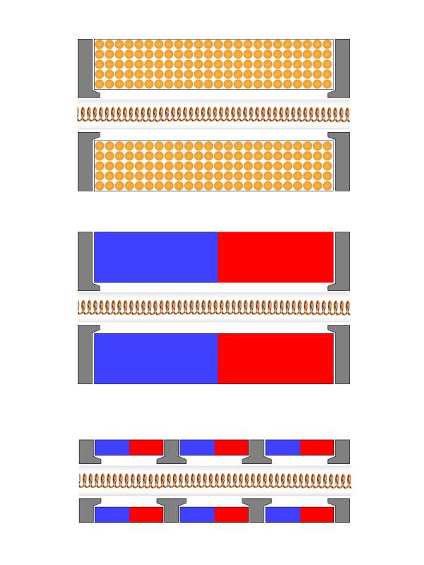
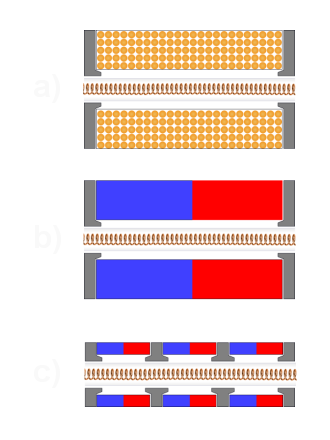
Figure 2: Variants of magnets: a) solenoid; b) permanent magnet; c) periodic permanent magnets
Electron Gun
The electron gun is similar in construction as in all cathode ray tubes. It consists of a indirect heated cathode, that must be heated to a temperature between 850° and 1 100° Celsius (≙ 1 500° to 2 000° Fahrenheit) to produce appreciable electron emission. A focusing grid with the same potential as the cathode (or a small negative bias up to −20 Volts relative to the cathode) directs the electrons in the desired direction. One or more anodes are used to generate the requisite electron velocity. The beam passes the anodes through a hole or a grid and travels through the slow wave structure.
The electron gun is covered by a shielding box to prevent hazardous radiation.
Surrounding Magnet
The surrounding magnet provides a magnetic field along the axis of the tube to focus the electrons into a tight beam. This magnet may be either a permanent magnet or a solenoid (electromagnetic) focusing element (see Figure 2a). A permanent magnet doesn't need a power supply and ensures that the magnetic field is always present. The disadvantage is that a permanent magnet doesn't provide an adjustment of the magnetic field to optimize the tubes performance.
If a single permanent magnet (see Figure 2b) is replaced by a number of smaller magnets then the size and total weight of the magnet structure is reduced (see Figure 2c).
The housing is usually made of aluminum to prevent the disturbing influence of ferromagnetic materials. Extrinsic magnetic materials can interfere with the uniform magnetic field and destroy the traveling wave tube. Therefore, the packaging of a traveling wave tube has oversized dimensions often.
attenuating cover
bunching
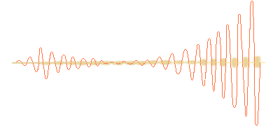
Figure 3: Amplified helix signal

attenuating cover
bunching
Figure 3: Amplified helix signal
Slow wave structure
Since the electron beam into the tube must obviously travel slower than the speed of light, there must be some means of slowing down the forward velocity of the electromagnetic wave. The electron beam speed of a TWT is about 10 to 50 percent of the speed of light. The speed depends on the cathode voltage that may be between 4 to 120 Kilovolts. The slowdown is done by means of a slow wave structure, on which the electromagnetic wave propagates.
Collector
The collector is a voltage electrode of the TWT. It's the same potential as the body of the tube, and this is usually on ground. In the absence of an input signal, the entire beam energy must be dissipated in the collector. Forced air-cooling or liquid cooling of the collector is necessary at high-power TWTs. High-power TWTs often use multi-stage collectors as shown in Figure 1.
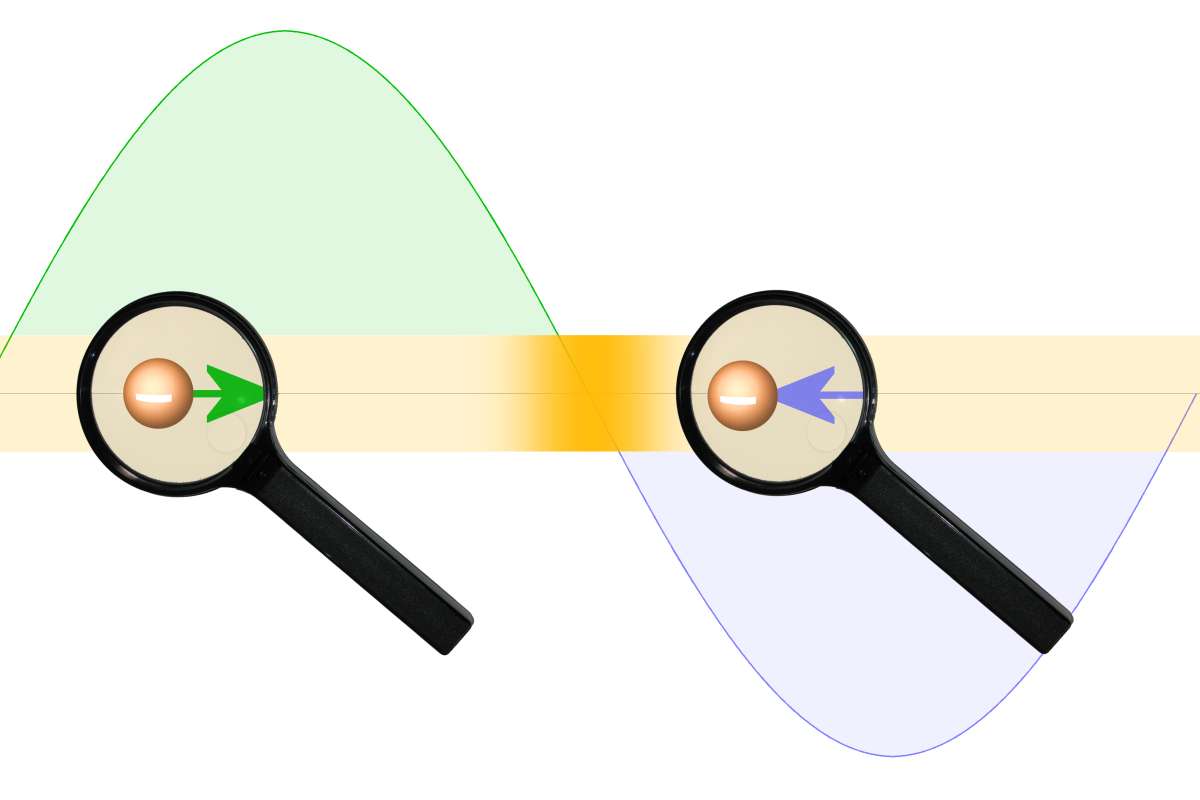
Figure 4: Electron-beam bunching
Functional describing
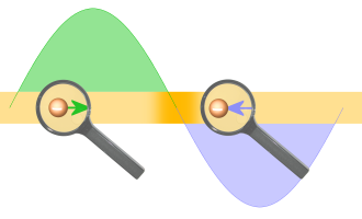
The input voltage creates an additional axial electric field that moves as fast as the electron beam on the wire of the helix. This electric field accelerates (in the positive half-wave) or decelerates (in the negative half-wave) the electrons in the electron beam. This process is called velocity modulation. If the electrons of the beam were accelerated to travel faster than the waves traveling on the wire, electron bunching would occur through the effect of velocity modulation. (see Figure 4)
By delivering energy to the electron beam, the power of the traveling wave decreases. The additional attenuator causes a decreasing to zero. This one attenuator also prevents any reflected waves from traveling back down the helix.
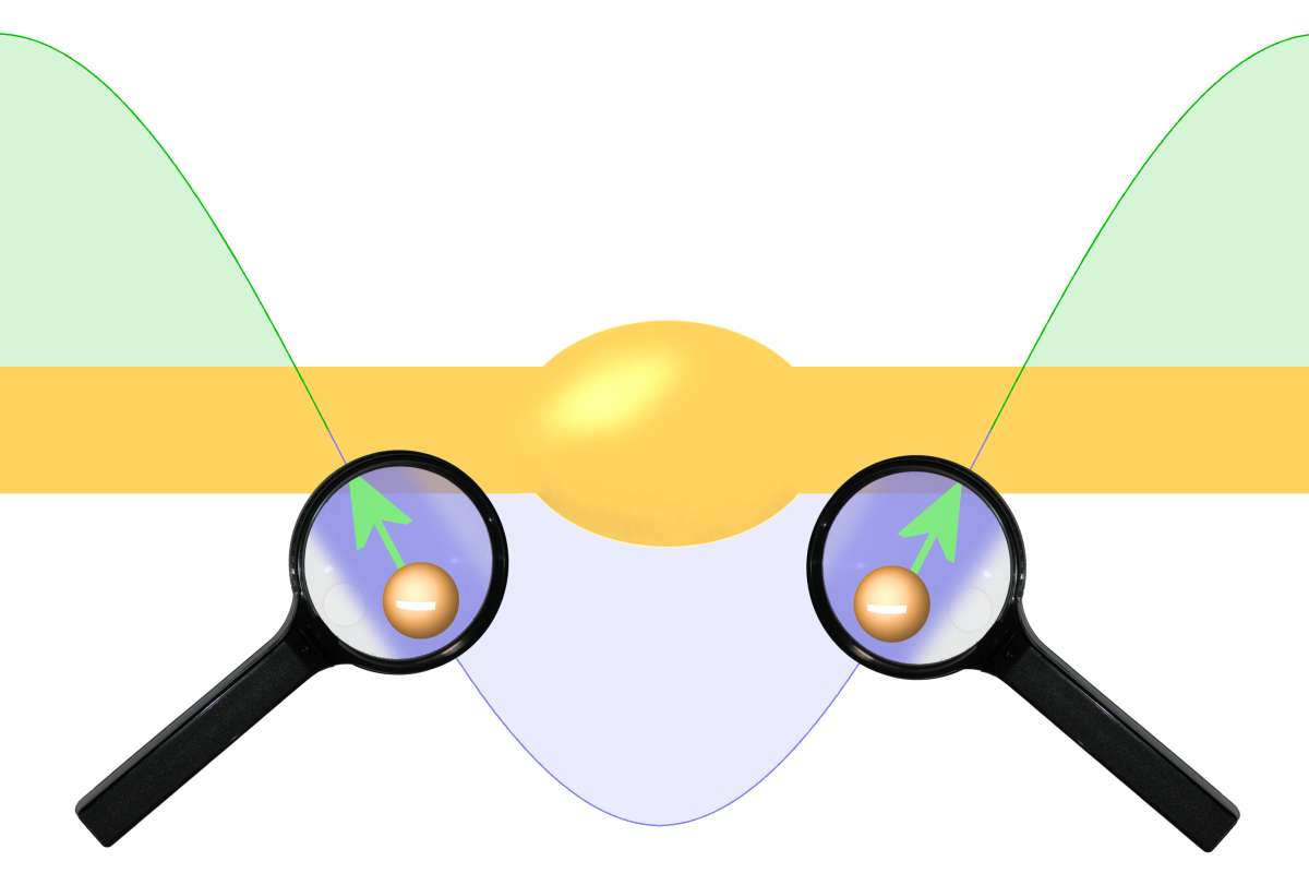
Figure 5: Repelling of the electrons in the wire of the helix
However, the velocity modulation is still effective in the electron beam. The faster electrons catch up with the slower electrons and bunching occurs. The electron- beam bunching already starts at the beginning of the helix and reaches its highest expression on the end of the helix. The electron bunches in the beam give up energy to the wire of the slow wave structure. They repel the electrons in the wire and generate a new one traveling wave in the helix. The energy from bunches would increase the amplitude of the traveling wave in a progressive action that would take place all along the length of the TWT.
The injection of the wave in the slow wave structure (as shown in Figure 5) causes a phase shift of −90 degrees relative to the initial waveform. When the electrons deliver their energy to the wave in the helix, they slow down. In some TWTs the helix is made narrower at the end of the tube therefore. This slows down the speed of the electromagnetic wave in the slow wave structure as well.
Characteristics of a TWT
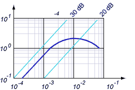
Figure 6: characteristic of a traveling wave tube
Figure 6: characteristic of a traveling wave tube
Power amplification
The attainable power-amplification is essentially dependent on the following factors:
- constructive details (e.g. structure and length of the helix)
- electron beam diameter (adjustable by the density of the focusing magnetic field)
- power input (see Figure 6)
- voltage UA2 on the helix
As shown in Figure 6, the gain of a given TWT has got linear characteristic of about 26 dB at small input power. If you increase the input power, the output power doesn't increase for the same gain. So you can prevent a saturation of e.g the following mixer stage in radar receiver. The relatively low efficiency of the TWT partially offsets the advantages of high gain and wide bandwidth.
Bandwidth
The gain of a TWT is affected by the interaction of the electrons with the electric field caused by the wave in the slow wave structure. The effectiveness depends on the frequency response of the slow wave structure. A helix may have a bandwidth of more than two octaves. If the slow wave structure contains resonant parts, then the bandwidth depends on its frequency response. The bandwidth of commonly used Coupled-Cavity TWTs is about 10 … 20 percent of the center frequency.
Noise Figure
The most important parameter for the use of the traveling wave tube as a pre-amplifier in radar receivers is the noise figure of the traveling wave tube. This determines the sensitivity of the receiver and thus the maximum range of the radar. The noise figure of recently used TWTs is 3 … 10 dB. There are three unavoidable sources of noise in a traveling wave tube:
- Shot noise results from the random emission of electrons of the cathode
- Velocity noise arises from different velocities of the emitted electrons.
- Johnson–Nyquist noise is the electronic noise generated by the thermal agitation of the electrons.
The noise figure depends on the size of most supply voltages of the traveling wave tube. For example, if the voltages at the electrodes are 5% less than the optimum values, the noise figure approximately doubles.
Different Slow Wave Structures
The previously described helix may be replaced by some other slow wave structure such as a ring-bar, ring loop, or coupled cavity structure. The structure is chosen to give the characteristic appropriate to the desired gain/bandwidth and power characteristics.
Contra-wound Helix
A contra-wound helix uses two helices wound in opposite directions. Both helices must be identical in dimensions. A contra-wound helix is less sensitive to backward waves interactions and therefore allows higher operating voltages, currents and power. The penalty for these advantages is that the bandwidth is less than that of a single helix.
Ring-Loop TWT
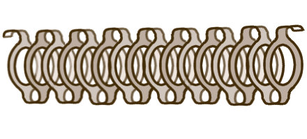
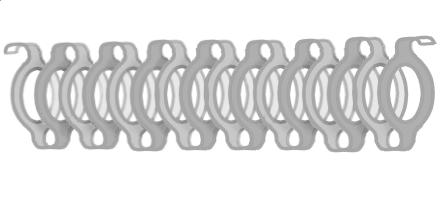
Figure 8: Ring-Loop slow wave structure
A Ring Loop TWT uses loops as slow wave structure to tie the rings together. These devices are capable of higher power levels than conventional helix TWTs, but have significantly less bandwidth of 5…15 percent and lower cut-off frequency of 18 GHz.
The feature of the ring-loop slow wave structure is high coupling impedance and low harmonic wave components. Therefore ring-loop traveling wave tube has advantages of high gain (40…60 Decibels), small dimension, higher operating voltage and less danger of the backward wave oscillation.
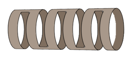
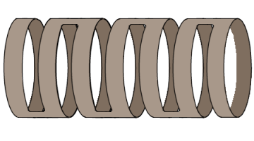
Figure 9: Ring-Bar slow wave structure
Ring-Bar TWT
The Ring-Bar TWT was developed from the contra-wound helix and has got the same characteristics likely the Ring-Loop TWT. This one slow wave structure is very easy to make by precise laser cuts in a thin copper pipe.
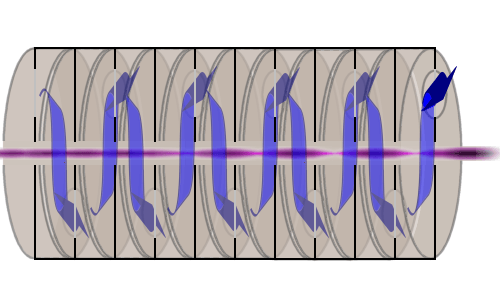
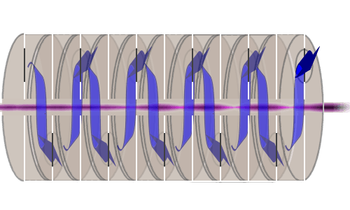
Figure 10: Coupled-cavity slow wave structure
Coupled-cavity TWT
The Coupled-cavity TWT uses a slow wave structure of a series of cavities coupled to one another. The resonant cavities are coupled together with a transmission line. The electron beam (shown in Figure 9 as red beam) is velocity modulated by an RF input signal at the first resonant cavity. This RF energy (displayed as blue arrow) travels along the cavities and induces RF voltages in each subsequent cavity.
If the spacing of the cavities is correctly adjusted, the voltages at each cavity induced by the modulated beam are in phase and travel along the transmission line to the output, with an additive effect, so that the output power is much greater than the power input.
Bildergalerie von Wanderfeldröhren
Picture gallery of Traveling wave tubes
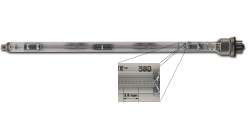
Figure 12: Russian low-power TWT UV-1B (cyrillic: УВ-1Б) used in P-37 “Bar Lock” (the measure in the detail enlargement is given for 20 windings)
Sources and ressorces:
- Alexander S. Gilmour jr.: ''Principles of Traveling Wave Tubes'', (Course-related training material), March 2014, ISBN 978-1-4951-0431-2

