What is AGC in receiver?
Automatic Gain Control Methods
Most radar receivers use some means to control the overall gain. This usually involves the gain of one or more IF amplifier stages. Manual gain control by the operator is the simplest method.
| English | Russian (Cyrillic) | German | |
| STC | sensitivity time control |
Временная Автоматическая Регулировка Усиления |
entfernungs- (also: zeit-) abhängige automatische Verstärkungsregelung (Siemens- Neudeutsch: GTC: Gain Time Control) |
| AGC | automatic gain control |
Шумовая Автоматическая Регулировка Усиления |
rauschabhängige Automatische Verstärkungs- Regelung |
| MGC | main gain control |
Ручная Регулировка Усиления |
Handregelung |
| log amp | logarithmic amplifier |
logarithmischer Verstärker |
Table 1: Gain control methods
Sensitivity Time Control (STC)
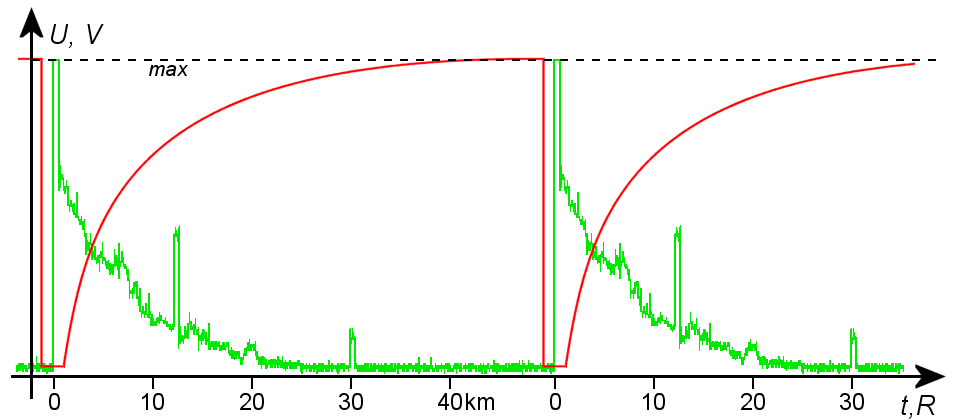
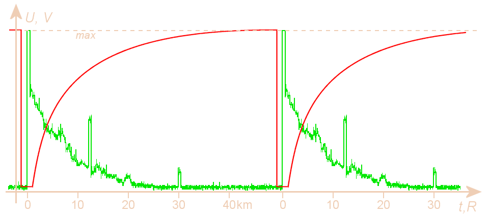
Figure 1: Diagram of the sensitivity time control
In radar receivers, the wide variation in return signal amplitudes make adjustment of the gain difficult. The adjustment of receiver gain for best visibility of nearby target return signals is not the best adjustment for distant target return signals. Circuits used to adjust amplifier gain with time, during a single pulse repetition period, are called STC circuits, or „swept gain attenuator”.
Sensitivity time-control circuits apply a bias voltage that varies with time to the IF amplifiers to control receiver gain. The Figure shows a typical stc waveform. When the transmitter fires, the stc circuit decreases the receiver gain to zero to prevent the amplification of any leakage energy from the transmitted pulse. At the end of the transmitted pulse, the stc voltage begins to rise, gradually increasing the receiver gain to maximum. In the ideal case the the receiver gain is proportionally to R4. In the practice this course is frequently approached by the arising e function for the store of a condenser.
The stc voltage effect on receiver gain is usually limited to approximately 50 miles. This is because close-in targets are most likely to saturate the receiver; beyond 50 miles, stc has no affect and the receiver operates normally.
Automatic Gain Control (AGC)

Figure 2: automatic gain control block diagram

Figure 2: automatic gain control block diagram

Figure 2: automatic gain control block diagram
Gain control is necessary to adjust the receiver sensitivity for the best reception of signals of widely varying amplitudes. A complex form of automatic gain control (agc) or instantaneous automatic gain control (iagc) is used during normal operation. The simplest type of agc adjusts the IF amplifier bias (and gain) according to the average level of the received signal. With agc, gain is controlled by the largest received signals. When several radar signals are being received simultaneously, the weakest signal may be of greatest interest. Iagc is used more frequently because it adjusts receiver gain for each signal.
The agc circuit is essentially a wide-band, dc amplifier. It instantaneously controls the gain of the IF amplifier as the radar return signal changes in amplitude. The effect of iagc is to allow full amplification of weak signals and to decrease the amplification of strong signals. The range of iagc is limited, however, by the number of IF stages in which gain is controlled. When only one IF stage is controlled, the range of iagc is limited to approximately 20 dB. When more than one IF stage is controlled, iagc range can be increased to approximately 40 dB.
Logarithmic Amplifier
The logarithmic amplifier is a nonsaturating amplifier that does not ordinarily use any special gain-control circuits. The output voltage of the logarithmic amplifier is a linear function of the input voltage for low-amplitude signals. It is a logarithmic function for high-amplitude signals. In other words, the range of linear amplification does not end at a definite saturation point, as is the case in normal IF amplifiers. Therefore, a large signal does not saturate the logarithmic amplifier; rather, it merely reduces the amplification of a simultaneously applied small signal.
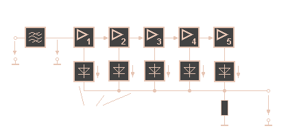
Figure 3: logaritmic amplifier block diagram
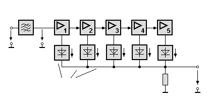
Figure 3: logaritmic amplifier block diagram

Figure 3: logaritmic amplifier block diagram
A typical circuit for obtaining a logarithmic response is shown in the figure. If detectors 2 to 5 were not present, the output voltage would be limited by the saturation point of the final IF stage, as it is in a normal IF section. However, when the final stage of the logarithmic amplifier is saturated, larger signals cause an increase in the output of the next to last stage.
This increase is detected by detector 2 and summed with the output of detector 1. This sum produces an increase in the output even though the final stage is saturated. Detector 3 causes the output to continue to increase after the second stage saturates. The overall gain becomes less and less as each stage saturates but some degree of amplification is still available. The proper choice of IF stage gains and saturation points produces an approximately logarithmic response curve.
Dynamic Swept Gain
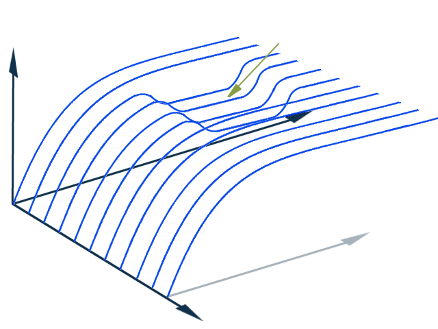
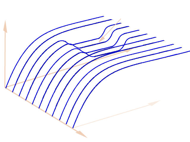
Figure 4: Diagrams of dynamic STC-curves
Local clutter levels dictate the magnitude of swept gain and differing requirements for swept gain are presented as the antenna rotates. Modern systems dynamically measure clutter levels for a large number of cells within the coverage area of the radar. These measurements are slowly adjusted to take account of changing clutter levels and used to set the swept gain attenuator to an appropriate level for the range azimuth cell currently being processed. In most cases, the values used are a variation on the normal static law.
This approach, while simple in principle, can risk reduction of MTI performance at the edges of clutter. This is due to abrupt changes in swept gain law destroying the integrity of the clutter amplitudes. Furthermore if long or compressed pulses are used, amplitude changes can affect the performance.
Swept gain is generally applied to pin diodes, which are biased to provide a reasonably linear characteristic.

