The Cassegrain Antenna
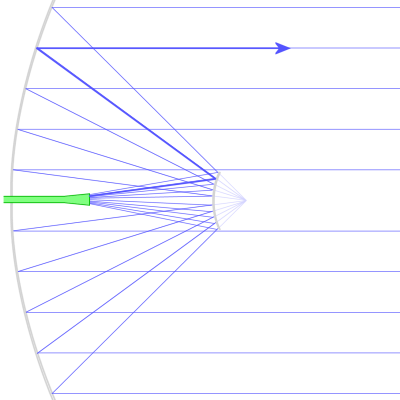
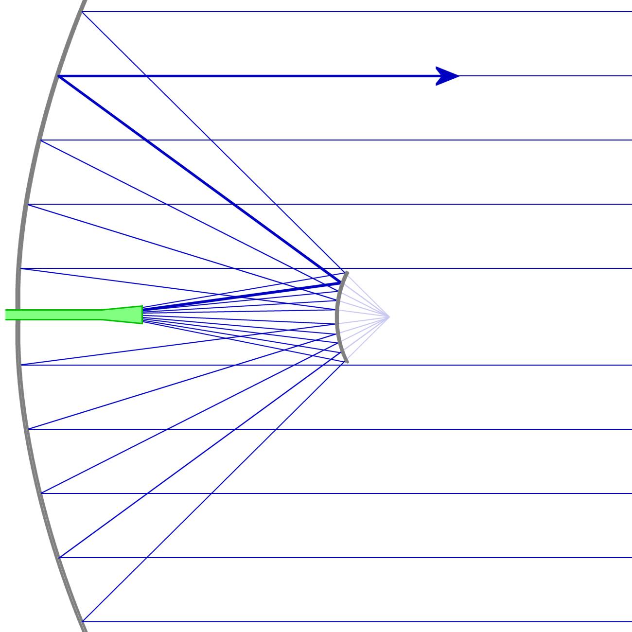
Figure 1: Principle of a Cassegrain antenna
The Cassegrain Antenna
Sieur Guillaume Cassegrain was a French sculptor who invented a form of reflecting telescope. A Cassegrain telescope consists of primary and secondary reflecting mirrors. In a traditional reflecting telescope, light is reflected from the primary mirror up to the eye-piece and out the side the telescope body. In a Cassegrain telescope, there is a hole in the primary mirror. Light enters through the aperture to the primary mirror and is reflected back up to the secondary mirror. The viewer then peers through the hole in the primary reflecting mirror to see the image.
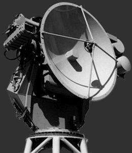
Figure 2: A Cassegray antenna used in a fire-control radar.
Figure 2: A Cassegray antenna used in a fire-control radar.
In telecommunication and radar use, a Cassegrain antenna is an antenna in which the feed radiator is mounted at or near the surface of a concave paraboloidal main reflector and is aimed at a convex hyperboloidal subreflector. Both reflectors have a common focal point. Energy from the feed unit (a feed horn mostly) illuminates the secondary reflector, which reflects it back to the main reflector, which then forms the desired forward beam.
| Advantages | Disadvantage: |
|---|---|
|
|
horizontal
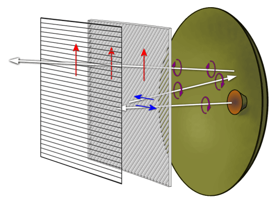
Figure 3: Principle of a polarization changing plate
horizontal
Figure 3: Principle of a polarization changing plate
There is a possibility to avoid the disadvantage the shadow of the secondary reflector and its mounting struts. The solution is found in antennae such as the tracking radar SkyGuard, manufactured in the company Oerlikon/Contraves AG. The subreflector reflects only horizontally polarized waves and let vertically polarized ones pass. The primary reflector reflects all waves. To achieve that, a plate is appropriately placed in front of the primary reflector instead of a hyperbolic metal reflector. This reflector consists of quart-wave plate (λ /4) with slits at an angle of 45° and a horizontally oriented metal grid.
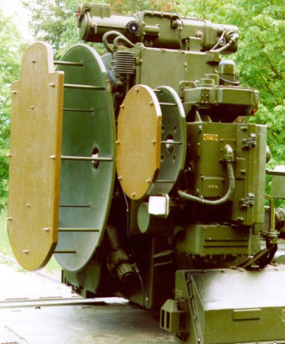
Figure 4: antennae of the tracking and command guidance radar for the SA-8 “Gecko”
The transmitted pulse leaves the horn radiator as, for instance, a left-hand circular polarized wave. The wave passes first the quarter-wave-plate and is transformed into a linear-horizontally polarized wave. This wave will be reflected on the horizontal strained wires. The wave passes the quarter-wave-plate again but from the other side. The orientation of the fins is mirrored now and appears rotated by 90 degrees. This has the effect, that the former change of polarization is rescinded. Therefore, a left-hand circular polarized wave travels back to the primary parabolic reflector.
The metallic reflection on the primary parabolic reflector will change the left-hand circularly polarized wave to a right-hand one. After passing the quarter-wave-plate a third time, this right-hand circular polarized wave will become a linear vertically polarized wave. This one can cross the subreflector grid without interaction and is emitted therefore vertically polarized toward targets.
In reception mode, the inverse path is followed.
The polarization changing plates you can see by the antennae of the tracking and command guidance radar system for the SA-8 “Gecko” surface-to-air missile (NATO reporting name “Land Roll”).