Transmitter Modules of Active Antenna

power
amplifier
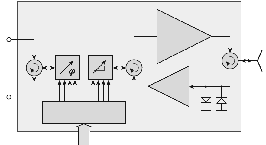
Figure 1: Design of transmitter/receiver modules of active antennas

power
amplifier
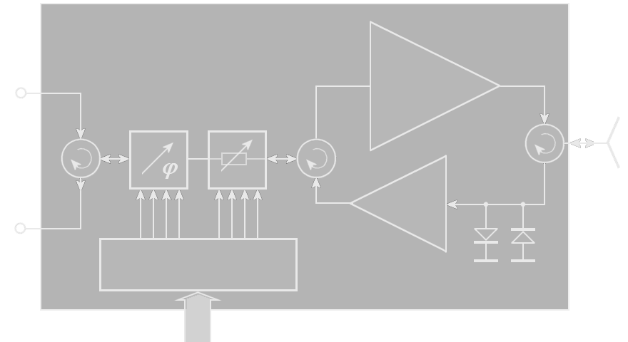
Figure 1: Design of transmitter/receiver modules of active antennas
Transmitter Modules of Active Antenna
Active phased array antennae are antennae at which the transmit power is produced by many rx/tx- moduls of low performance on the antenna directly. E.g.: the Tornado-Nose-Radar and the air defense radar RRP-117. These antennae are described in an earlier chapter. The special transmitter modules come up on this page.
An active phased array uses a special type of solid-state transmitter module. The arrangement applied to most active phased arrays is shown on the figure.
All components are assembled in one single T/R module. This module integrates the electronic phase shifter, the digital controlled attenuator, the solid-state power amplifier, the low noise amplifier (LNA) and two circulators and a Duplexer. It is also usual for the module to have self test and status features so that the overall performance of the system can be assessed (BITE). A limiter is sometimes added between the LNA and antenna. This reduces very strong incoming signals from jammers or large targets (with very high Radar Cross-Section) close to the radar.
The limiter also protects the receiver against duplexer failure. A simple limiter implementation consists of two pin diodes connected in parallel but with inverted polarities.
In many recently developed radar sets like the RRP-117 are used power-amplifier transmitters. This transmitter works multiplexed with two frequencies. These two frequencies are linear FM- modulated for the pulse compression. By this pulse compression method the radar don't need so high pulse power, therefore a good maximum range is obtained despite the lower pulse power limited by semiconductor amplifiers. Every row of the phased array antenna has got an own solid-state power-amplifier module and an own receiver. The combination of the received signals by the monopulse antennae concept is carried out after the mixer stages on the IF-frequency. The power moduls providing with needed currents is carried out via a bus system.
Gallery of transmitter modules

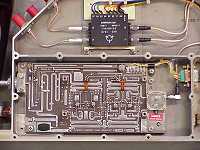
Figure 3: An open receiver block: top the black box with the control circuitry including phase shifter, circulators and attenuator, bottom the low-noise preamplifier.

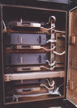
Figure 4: Standardised Modular Transmit-/Receive-Module
(Courtesy of
Cassidian Ulm,
former
EADS Defence & Security)

