Pulse Radar

Figure 1: Runtime measurement by radar
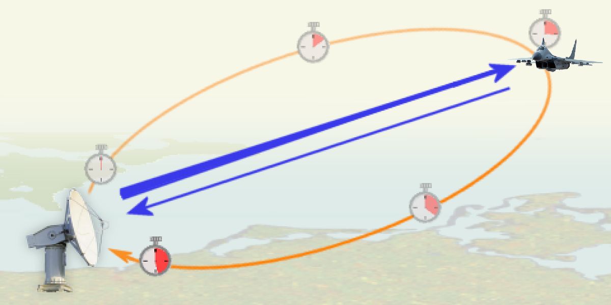
Figure 1: Runtime measurement by radar

Pulse Radar
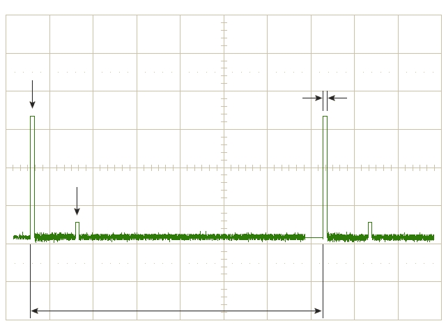
Figure 2: Radar pulse relationships
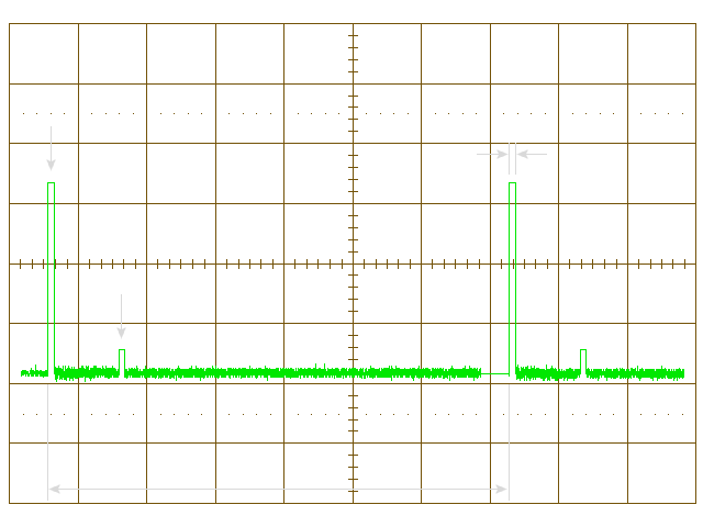
Pulse radar emits short and powerful pulses and in the silent period receives the echo signals. In contrast to the continuous wave radar, the transmitter is turned off before the measurement is finished. This method is characterized by radar pulse modulation with very short transmission pulses (typically transmit pulse durations of τ ≈ 0,1 … 1 µs). Between the transmit pulses are very large pulse pauses Τ >> τ, which are referred to as the receiving time (typically Τ ≈ 1 ms) as shown in Figure 2. The distance of the reflecting objects is determined by runtime measurement (at a fixed radar) or by comparison of the characteristic changes of the Doppler spectrum with the values for given distances stored in a database (for radar on a fast-moving platform). Pulse radars are mostly designed for long distances and transmit a relatively high pulse power.
Important distinguishing feature to other radar method is the necessary time control of all processes inside the pulse radar. The leading edge of the transmitted pulse is the time reference for the runtime measurement. It ends with the transition of the rising edge of the echo signal in the pulse top. Systematic delays in signal processing must be corrected when calculating the distance. Random deviations influence the accuracy of the pulse radar.
Transmit Signal
The waveform of the transmitted signal can be described mathematically as:
| s(t) = A(t)· sin[2πf(t)·t + φ(t)] | (1) |
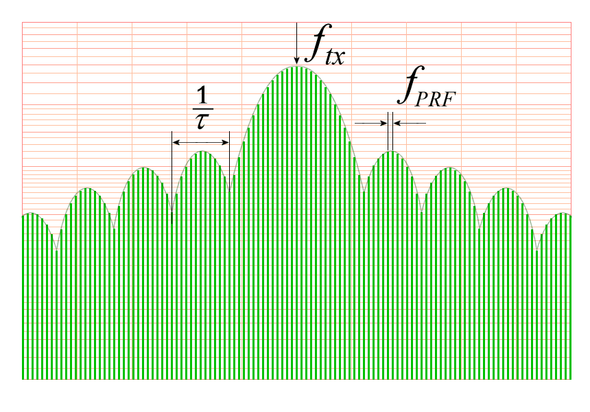
Figure 3: Frequency spectrum of a sequence of rectangular pulses in the vicinity of the transmission frequency ftx
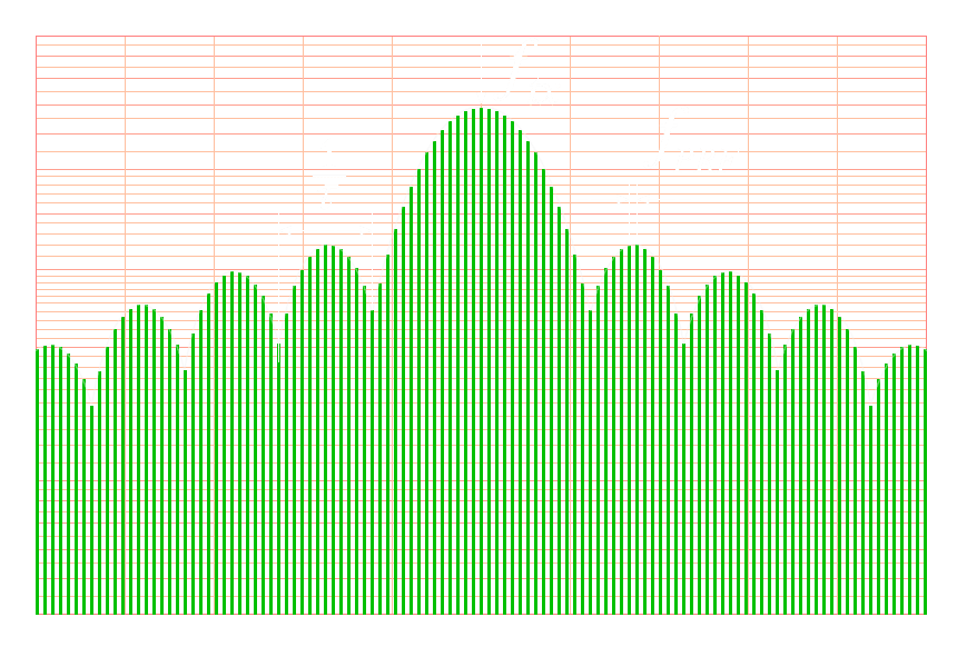
Figure 3: Frequency spectrum of a sequence of rectangular pulses in the vicinity of the transmission frequency ftx
The function A(t) is a variation of the amplitude in the function of time t - ie an amplitude modulation. In the simplest case, the transmitter is for a short time switched on (for the time τ) and remains in the rest of the time in the "off position". A(t) is then in the transmission case = 1, otherwise = 0. The function of time is then determined by the pulse repetition frequency and the duty cycle. Since the radar returns are subject to various losses, an actual amplitude modulation makes little sense except for just this switching function (On/off keying). The envelope of the frequency spectrum of a sequence of rectangular pulses is represented by a (sin x)/x function. The essential parts of the transmission power (note the logarithmic scale of the ordinate in Figure 3) are in a region BHF = 2/τ in the vicinity of the transmission frequency ftx.
The pulse repetition frequency fPRF and the duration of the transmitted pulse τ and the receiving time (Τ − τ) have an influence on the performance of the radar, e.g. the minimal measuring range (the transmit pulse must have completely exited the antenna) and the maximum unambiguous range (the echo signal must be received in the time before the next transmission pulse).
The duration of the transmit pulse τ substantially affects the range resolution ΔR of pulse radar. The range resolution is:
| ΔR = 0.5·τ·c | (2) |
The shorter the transmission pulse, the closer one behind the other two reflectors may be positioned so as to be nevertheless detected as two reflectors and not as one large object. The transmitter bandwidth BHF of the pulse radar increases with decreasing pulse width:
| BHF = τ−1 | (3) |
The shortening of the pulses limits the maximum range in the case of simple pulse modulation. Under these conditions, the pulse energy Ep can be increased only by the pulse power PS at a required range resolution.
For the maximum range of the pulse radar, the pulse energy is crucial, and not its pulse power:
| Ep = Ps· τ = Pav· Τ = | Pav | where | Ep = energy content of the pulse PS = transmission pulse power Pav = average power |
(4) |
| fPRF |
Significant improvements in this situation can be achieved with the internal modulation of the transmit pulse (intra-pulse modulation). The relationship between the duration of the transmit pulse and the duration of the received pulse is resolved by the pulse compression in the receiver. A location of various reflectors and the measurement of its individual range can also be carried out within the duration of the transmit pulse.
The function φ(t) in equation (1) is the expression for a phase shift of the whole signal. The initial phase of the transmitted signal can either be known and can be predictable (due to the generation of oscillation). In this case, the pulse radar is attributable to the fully coherent radars. The actual phase angle can also be known but the initial state can be unpredictable. Then the radar is one of the pseudo-coherent radars. If this initial phase completely indeterminate (chaotic), then the radar is one of the non-coherent radars. Only with a possible phase-encoded Intra Pulse modulation, this function gets more importance.
Echo Signal
Usually, it is assumed that the duration of the transmitted pulse is equal to the duration of the reflected echo pulse. Thus, in the ratio of the transmitted power and the received power (which is used in the fundamental radar range equation) can be dispensed with a time specification.
- By the reflection of the transmit signal the spectrum may be modified:
- It can occur additional harmonics to the carrier frequency.
- The carrier frequency can be imposed on one or more Doppler frequencies.
- The direction of the polarization can be changed.
- The pulse duration of the echo signal is not constant. The duration of the reflected pulse can be considerably stretched by interference from reflections at areas with slightly different distances (and following different run times).
All together: the echo signal is subject to so many influences that the waveform and the shape of the echo signal in the result must be regarded as unknown. Nevertheless, in order to build an optimal matched receiver or an optimal matched filter, multiple receiving channels must be set up in parallel, taking into account all the possible deformations of the signal. In a selection circuit, the echo signal with the best (greatest-of) Signal to Noise Plus Interference Ratio (SNIR) is then further processed. The “position” of the greatest-of-switch is also saved as important information for the identification of this echo signal.
In general, the receiving bandwidth is kept as small as possible, so not much unnecessary noise is received. Therefore, to select the bandwidth only with BHF = 1/τ for a simple pulse radar. The influence of the noise can be suppressed in the receiver using of pulse integration. Here, a sum of pulse periods is formed. The reflecting object is assumed to be stationary during the time of these pulse periods. Since the noise is randomly distributed, thereby the sum of the noise cannot reach the sum of the echo signals. The signal-to-noise ratio is improved by this measure.
Design, Block Diagram
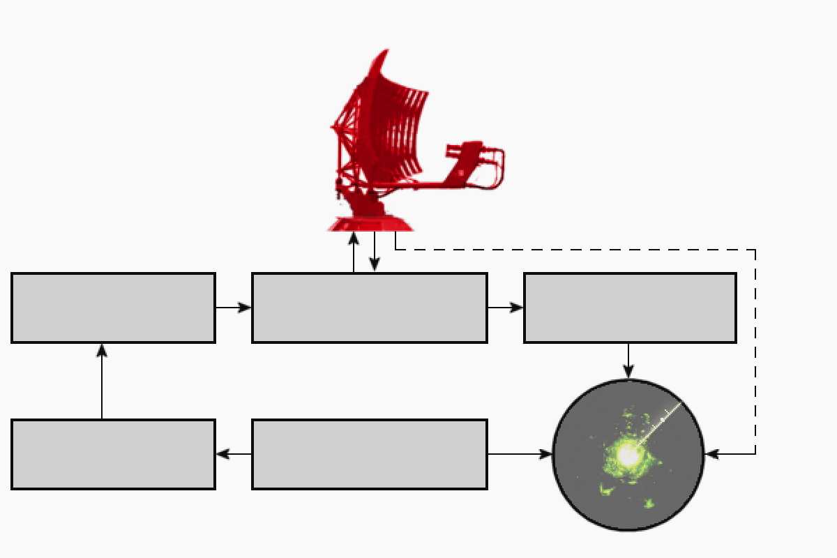
Figure 4: Block diagram of a monostatic pulse radar
The construction of a pulse radar depends on whether transmitter and receiver are at the same site (monostatic radar) or whether both components are deployed at completely different locations (bistatic radar).
A monostatic pulse radar, in addition to the compact design has the advantage that the important for pulse radars timing devices can be concentrated in a central synchronization block. Internal runtimes of the radar triggers can thus be kept low. An elaborate radar antenna can be used by means of a multiplexer for both transmitting and receiving.
The disadvantage is that often the highly sensitive radar receiver must be switched off by a duplexer for its own protection against the high transmission power. During this time it cannot receive anything.
Description of the modules in the block diagram
In a bistatic pulse radar, the receiver is equipped with its own antenna in a different location as the transmitter. This has the advantage that the receiver can operate without significant protective measures against to a high transmission power. In the simplest case, a network is constructed from extra receiver locations to an existing monostatic pulse radar. Example given: weather radar Poldirad in Oberpfaffenhofen, Germany (near Munich). The receiving antennas are not very directionally: they must be able to receive from several directions simultaneously. The disadvantage here is the very complex synchronization. Simultaneously with the echo signals, the receiver must also receive the direct transmission signal. From this signal and the known distance to the transmitter, a sync signal must be generated. Principal military application of bistatic configurations are the Over-The-Horizon (OTH) Radars.
The passive radars are a variant of the bistatic radar. They parasitically use a variety of RF emissions (radio or television stations, or external pulse radars) The passive radar calculates the position of the targets from the difference between the time of the direct path of the signal and the additional running time of the reflected echo signals. Ambiguities in the measurement can be excluded on the one hand by direct direction finding involving spurious emissions of the target or by synchronization of two passive radars working at different locations.
Applications
Pulse radars are designed mainly for long distances. The main application is still the military area. Other applications include air traffic control, weather observation (especially precipitation radar) as well as the satellite-based remote sensing of the earth's surface.