Radar B-Scope

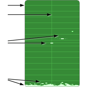
Figure 1: B-Scope
Radar B-Scope
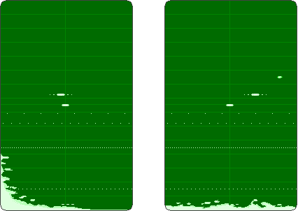
The B-Scope shows a picture like a Cartesian diagram. It provides a 2-D “top down” representation of space. The horizontal axis (abscissa) typically represents the measurement of the azimuth (bearing), and the vertical axis (ordinate) represents the measurement of the range. Signals appear as bright spots.
B-scope displays were common in airborne and fire-control radars in the 1950s and 60s, which were mechanically or electronically scanned from side to side, and sometimes up and down as well. The center of the bearing usually is movable through hand wheels in fire-control radars. The antenna turntable then is turned into the new direction. The screens middle is defined as the main reception direction of the antenna normally. The bearing area is covered through an electro-mechanical or electronic beam steering.
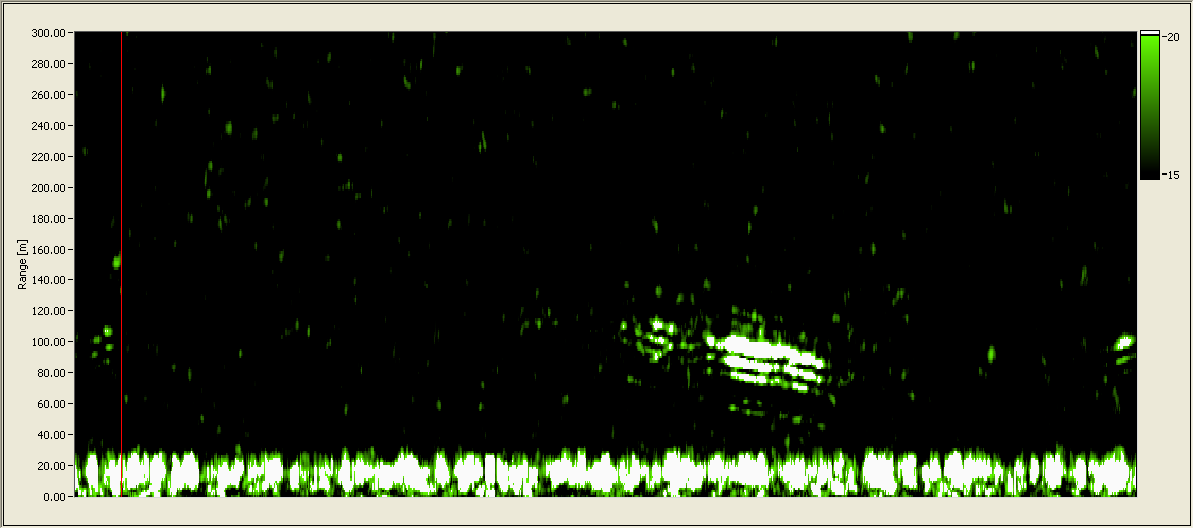
The used designation “B-scope” is ambiguous sometimes. The term refers to two completely different types of scopes. In radar devices without measurement of the azimuth angle, the term “B-scope” is also used (e.g.: Ground Penetration Radars). The abscissa is a time coded scale then, and shows a history of the pulse periods.


