Antenna with Cosecant Squared Pattern
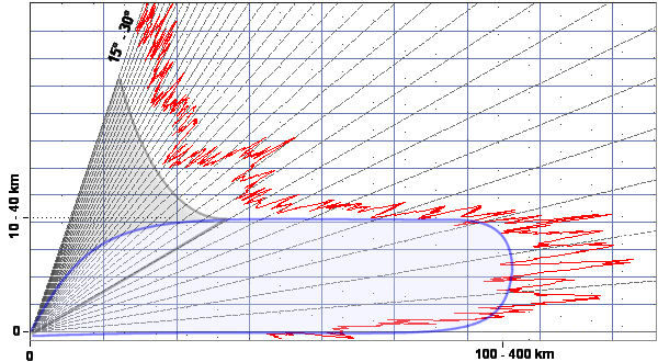
Figure 1: Vertical projection of the radiation pattern of an antenna with cosecant-squared characteristic
Figure 1: Vertical projection of the radiation pattern of an antenna with cosecant-squared characteristic
Antenna with Cosecant Squared Pattern
Antennae with constant height pattern or cosecant-squared pattern are special designed for air-surveillance radar sets. These permit an adapted distribution of the radiation in the beam and causing a more ideal space scanning. This antenna pattern can get the required elevation coverage where the received power is independent of the radar range for a constant height target It is a means of achieving a more uniform signal strength at the input of the receiver as a target moves with a constant height within the beam.
There are a couple of variation possibilities, to get a cosecant-squared pattern in practice:
- deformation of a parabolic reflector
- a stacked beam by more horns feeding a parabolic reflector
- an antenna group with either different spacing or different feeding of elements
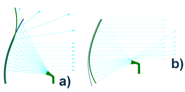
Figure 2: a deviating from the ideal parabolic shape of the reflector curvature
a) “upper lip”
b) “lower lip”
Figure 2: a deviating from the ideal parabolic shape of the reflector curvature
a) “upper lip”
b) “lower lip”
Deviating shape of the parabolic reflector
In the practice a cosecant-squared pattern can be achieved by a deformation of a parabolic reflector. A radiator is in the focal point of a parabolic reflector and produces a relatively sharply bundled radiation lobe since the rays leave the reflector parallelly in the ideal case. To get the cosecant-squared pattern, a part of the radiated energy must be turned up. A possibility consists in lower bending of the top of the reflector. The part of the rays which falls to the less bent area (in the top) is reflected up now. A possible method analogously for this one is, to bend the lower part of the reflector more intense.
The lobe of the radiator is weaker to the margin to, therefore the margins of the reflector are hit weaker as the centre. By the fact that the rays turned up don't have a large power density, the maximum range in the higher elevation is limited with that.
The ideal pattern as shown in Figure 1 is a nearly rectangular shape with rounded corners. In reality, the diagram is superposed with a number of side lobes mainly on the back at higher elevation angles. The shape of all these back side lobes is combined into a nearly parabolic slope. This gives in near range an additional gain required for constant echo strength after sensitivity time control.
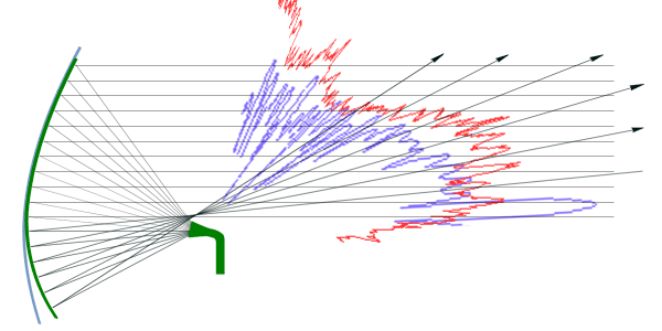
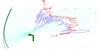
Figure 3: Cosecant-squared pattern achieved by displacing the reflector surface from the original parabolic shape
Stacked Beam Cosecant Squared Pattern
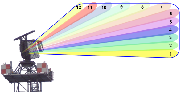
Figure 3: Stacked beam cosecant-squared pattern
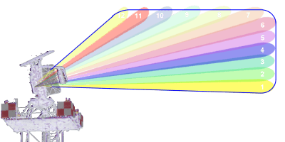

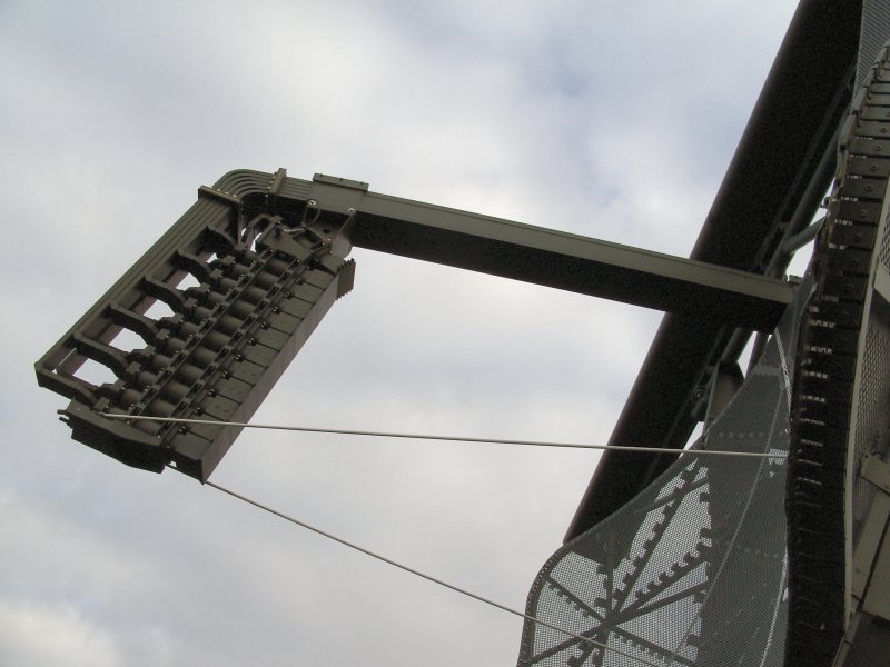
Figure 4: An arrangement of twelve feed horns at the antenna of the radar set ASR 910 achieves a stacked beam cosecant-squared pattern
Figure 4: An arrangement of twelve feed horns at the antenna of the radar set ASR 910 achieves a stacked beam cosecant-squared pattern
A cosecant-squared pattern can be achieved by two or more horns feeding a parabolic reflector.
Every feed horn already emits directionally. If one distributes the transmit power unevenly on the single radiating elements, then the antenna pattern approaches a cosecant-squared pattern.
At use of several receiving channels a height allocation also can be carried out. The targets can be assigned to beams with defined elevation there.
The cosecant-squared pattern isn't restricted to parabolic reflectors. This can be realized also with other kind of antennae. At an antenna array with Yagi- antennae the pattern is achieved by interference of the direct wave with this at the earth's surface reflected quotas. (1. Fresnel zone).
The Term „Cosecant square”
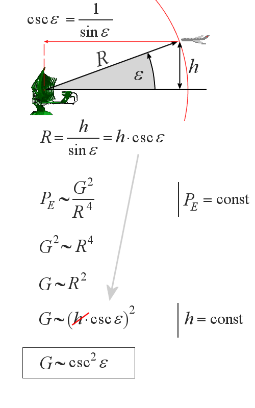
The term “Cosecant” sounds very much like a mathematical triangular function. This is right! It is equal to the reciprocal value of the sine function. However, what does this term have to do with our antenna?
The height H and the range R define the elevation angle ε…
We remember what is written here in the introduction:
If we convert the formula according to the range and using the trigonometric relation mentioned above already appears the term “Cosecant” - furthermore…
What there still was with the “…uniform signal strength…”
We can derive this dependence from the
radar equation:
If the echo has a uniform signal strength at the input of the receiver
than the range is dependent on the square of the
antenna gain in the fourth power linearly.
We can shorten the powers arithmetically…
We replace the range by the formula with the upper „Cosecant”-formula now.
According to definition mentioned above the height also shall be constant.
That means, we can shorten the height too without changing the dependence.
So we get the mathematical describing of an antenna with a “cosecant-squared pattern”!