Receiver Channels
Amplitude Channel

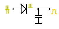
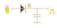
Figure 1: simplest demodulator: envelope curve detector

Figure 1: simplest demodulator: envelope curve detector
The signal at the receiver output can have different properties. In the simplest case, the intermediate frequency is rectified by a diode and at the receiver output you can measure a so-called video signal. Since this video signal of the receiver includes frequencies up to 5 MHz (depending on the bandwidth), one cannot speak as with a radio receiver of low frequency but the principle of the demodulation is the same to a radio in the frequency domain medium wave.
This type of receiver output signal provides the advantage of a maximum sensitivity of the radar receiver. As major disadvantages are mentioned, that a Doppler frequency analysis is not possible and that all interferences overlay the radar signal. Therefore, such an output signal in analog radars was shown only in the far area on the screen, an area in which there are no interference by fixed targets (clutter).
This kind of receiver output is only used for the following applications in modern surveillance radars:
- for detecting interference situations (Jamming),
- for the detection of weather phenomena (comparable to the previously used rain reject)
- and a measurement output for the BITE.
Coherence Channel
To detect a Doppler frequency (and thus a speed), the received signal must pass through a demodulator which is phase-sensitively. (phase detector). At the output of the receiver, a signal of intermediate frequency is provided. This signal was amplified but only changed through a dynamic range compression up to this point.
Modern surveillance radars use this pathway only because a Doppler frequency analysis provides valuable information for automatic target detection.
