Duplexer

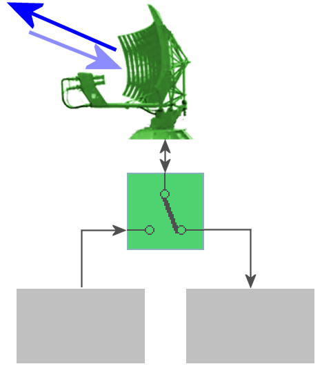
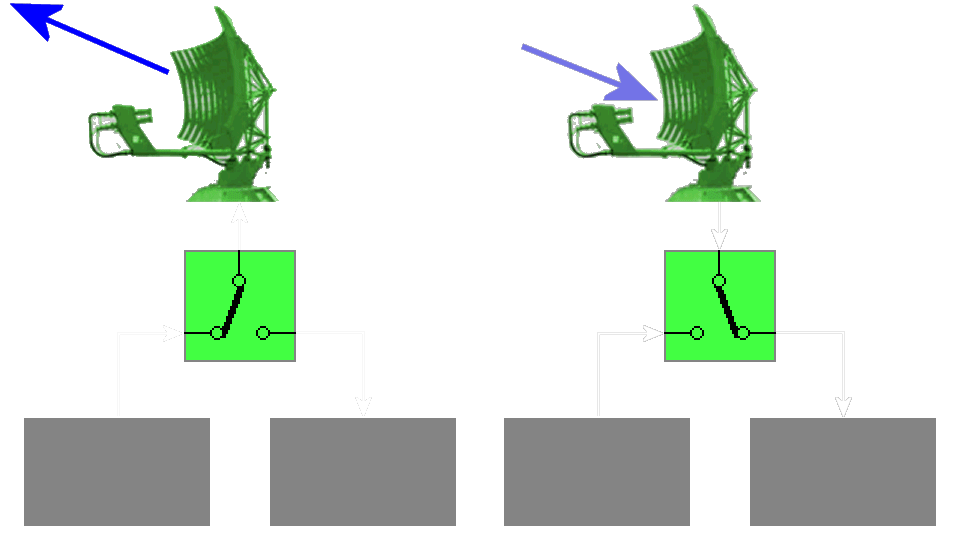
Figure 1: simplified functional block diagram of radar using a duplexer

Figure 1: simplified functional block diagram of radar using a duplexer
Whenever a single antenna is used for both transmitting and receiving, as in radar system,
an electronic switch must be used! Switching systems of this type are called duplexers.
Switching the antenna between the transmit and receive modes presents one problem; ensuring
that maximum use is made of the available energy is another. The simplest solution is to use a
switch to transfer the antenna connection from the receiver to the transmitter during the
transmitted pulse and back to the receiver during the echo pulse. No practical mechanical switches
are available that can open and close in a few microseconds.
Therefore, electronic switches must be used.
Duplexers are constructed in many forms, such as
- Ferrite Circulators (hybrid-ring duplexer) or
- resonant cavity coaxial or waveguide systems,
- with TR- and ATR- tubes,
- or with pin diodes
Since waveguide and hybrid-ring duplexers are most common in radar systems.
The simplest solution would be here to use a ferrite circulator. However, it is complicated to make circulators for top performances up to many 100 kW in the practice. In addition, circulators have a decoupling of hardly more as 30 to 40 dB and cannot protect the highly sensitive receiver from the high transmit powers sufficiently. On the other hand a circulator can provide the receiver with an echo signal during the transmission time. It has not the limitations of a so-called blind range like other duplexer systems. Circulators as duplexer are predetermined for radar sets with a very low transmitter's peak power, like the DPR886
Therefore TR- and ATR-tubes are used. Unfortunately, duplexers need a reaction time situated in the nanosecond area. The full transmit power reaches the receiver in this time! You may increase the speed with which the gap breaks down after the transmitter fires by placing a voltage of about 800 to 1200 V across the gap electrodes. This voltage is known as keepalive voltage. This action provides for rapid ionization when the transmitter pulse arrives.
Efficient pin diodes don't have this disadvantage.
