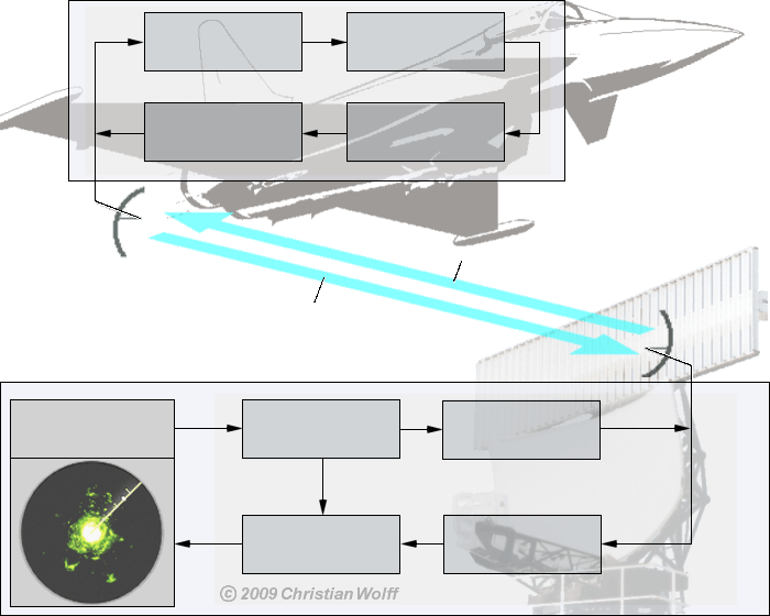
Functional Block Diagram of Secondary Radar

Transponder
Receiver
Decoder
Transmitter
Coder
Interrogator
Coder
Transmitter
Decoder
Receiver
PPI-screen
Synchronizer of
Primary Radar
Primary Radar
Interrogation Path
(Uplink)
(Uplink)
Replay Path
(Downlink)
(Downlink)
Figure 1: Block diagram of a secondary radar

Transponder
Receiver
Decoder
Transmitter
Coder
Interrogator
Coder
Transmitter
Decoder
Receiver
PPI-screen
Synchronizer of
Primary Radar
Primary Radar
Interrogation Path
(Uplink)
(Uplink)
Replay Path
(Downlink)
(Downlink)
Figure 1: Block diagram of a secondary radar

Transponder
Receiver
Decoder
Transmitter
Coder
Interrogator
Coder
Transmitter
Decoder
Receiver
PPI-screen
Synchronizer of
Primary Radar
Primary Radar
Interrogation Path
(Uplink)
(Uplink)
Replay Path
(Downlink)
(Downlink)
Figure 1: Block diagram of a secondary radar
Functional Block Diagram of Secondary Radar
In the interrogator on the ground:
The secondary radar set needs a synchronous impulse of the (analogous) primary radar set to the synchronization of the indication.
- The chosen mode is encoded in the Coder. (By the different modes different questions can be defined to the airplane.)
- The transmitter modulates these impulses with the RF frequency. Because another frequency than on the replay path is used on the interrogation path, an expensive duplexer can be renounced.
- The antenna is usually mounted on the antenna of the primary radar set and turns synchronously to the deflection on the monitor therefore.
In the aircrafts transponder:
A receiving antenna and a transponder are in the airplane.
- The receiver amplifies and demodulates the interrogation impulses.
- The decoder decodes the question according to the desired information and induces the coder to prepare the suitable answer.
- The coder encodes the answer.
- The transmitter amplifies the replay impulses and modulates these with the RF reply-frequency.
Again in the interrogator on the ground:
- The receiver amplifies and demodulates the replay impulses. Jamming or interfering signals are filtered out as well as possible at this.
- From the informations “Mode” and “Code” the decoder decodes the answer.
- The monitor of the primary radar represents the additional interrogator information. Perhaps additional numbers must be shown on an extra display.
