Radar A- Scope
 p>Figure 1: View of an A-scope
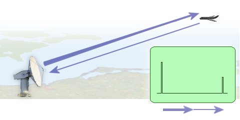
Figure 1: Principle of operation of an A-scope
Radar A- Scope
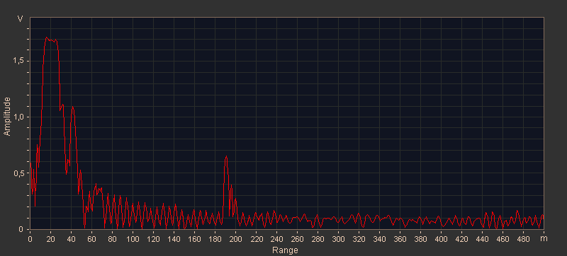
The A-scope display, shown in the figure, presents only the range to the target and the relative strength of the echo. Such a display is normally used in weapons control radar systems. The bearing and elevation angles are presented as dial or digital readouts that correspond to the actual physical position of the antenna. The A-scope normally uses an electrostatic-deflection crt. The sweep is produced by applying a sawtooth voltage to the horizontal deflection plates. The electrical length (time duration) of the sawtooth voltage determines the total amount of range displayed on the crt face.
The A- scope display is using in older radar sets only as monitoring oscilloscope. In modern digital radar sets don't exist a similar video signal of the backscatter. The target messages are transmitted to the displays as a digital word. There isn't any possibility to get a synchronizing signal for these asynchronous serial digital signals. Well, the oscilloscope can get an internal trigger only. Therefore it is impossible to analyze the bit sequence with a simple oscilloscope. The one and only statement is possible seeing this picture: a digital word exists on this line, which means, obviously the driver module for this line works.
Picture gallery of A- Scopes
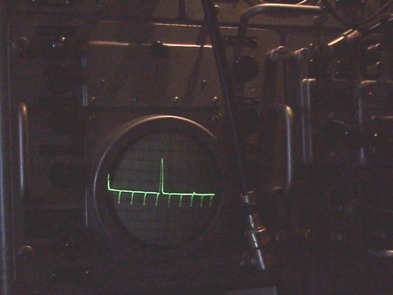
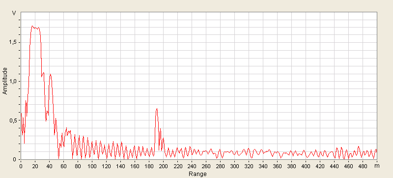
Figure 3: the attempt to see digital serial signals with an A-scope
Figure 4: back from digital data converted analog signals, such as those are displayed in the didactic primary radar DPR886.