Radar Cross-Section
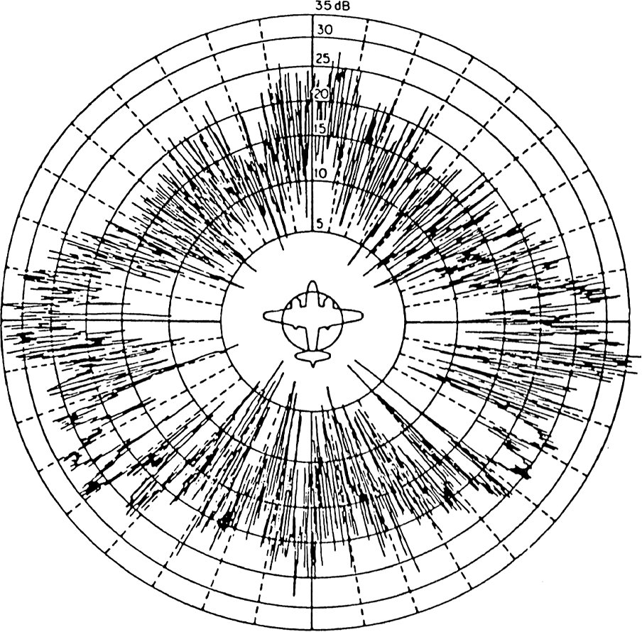
Figure 1: the experimental radar cross-section of the B-26 aircraft at 3 GHz frequency as a function of azimuth angle (after Skolnik)
Figure 1: the experimental radar cross-section of the B-26 aircraft at 3 GHz frequency as a function of azimuth angle (after Skolnik)
Radar Cross-Section
The radar cross-section σ is a specific parameter of a reflective object that depends on many factors, and which has units of m². The calculation of the radar cross-section is only possible for simple objects. The surface area of simple geometric bodies depends on the shape of the body and the wavelength, or rather on the ratio of the structural dimensions of the object to the wavelength. If absolutely all of the incident radar energy on the target were reflected equally in all directions, then the radar cross-section would be equal to the target's cross-sectional area as seen by the transmitter. In practice, some energy is absorbed and the reflected energy is not distributed equally in all directions. Therefore, the radar cross-section is quite difficult to estimate and is normally determined by measurement.
The target radar cross-sectional area depends of:
- the airplane’s physical geometry and exterior features,
- the direction of the illuminating radar,
- the radar transmitters frequency,
- the used material types.
The use of stealth technology to reduce radar cross-section increases the survivability and decreases the target detection of military aircraft. But the stealth technology depends of the used radar transmitters frequency and has none effect against VHF- radars like P–12 or P-18, both used by serbian air defense units during the Kosovo war.
Calculation of the radar cross-section
Radar cross-section (RCS) is the measure of a target's ability to reflect radar signals
in the direction of the radar receiver, i.e. it is a measure of the ratio of backscatter density
in the direction of the radar (from the target) to the power density that is intercepted by the target.
Since the power is distributed on the shape of a sphere, a small part of this
((4·π·r2)) can be received by the radar.
Radar cross-section σ is as defined as:
| σ = | 4·π·r2·Sr | mit |
σ: measure of the target's ability to reflect radar signals in direction of the radar receiver, in [m²] St: power density that is intercepted by the target, in [W/m²] Sr: scattered power density in the range r, in [W/m²] |
(1) |
| St |
The RCS of a target can be viewed as a comparison of the strength of the reflected signal from a target to the reflected signal from a perfectly smooth sphere of cross-sectional area of 1 m².
The following backscattering formulas from shapes occurs in an optical independent of frequency region.
reflected signal from a spherical shape |
| |||||
 reflected signal from a cylinder |
| |||||
reflected signal from a flat plate |
| |||||
reflected signal from a tilted plate | ...Real as the previous example. Unusual feature: the reflected energy is reflected in another direction. Well, the transmitting radar cannot receive this energy. Therefore there are bistatic radars at which the transmitter and the receivers are separated from each other spatially. |
Table 1: RCS for geometrically bodies
RCS for Point-Like Targets
| Targets | RCS [m2] | RCS [dB] |
| bird | 0.01 | -20 |
| man | 1 | 0 |
| cabin cruiser | 10 | 10 |
| automobile | 100 | 20 |
| truck | 200 | 23 |
| corner reflector | 20379 | 43.1 |
Table 2: RCS for Point-Like Targets
Some targets have large values of RCS owing to their size and orientation and consequently, reflect a large portion of the incident power. The beside table shows the values of RCS for some targets at X-Band
(Table from: M. Skolnik, “Introduction to radar systems”, 2nd Edition, McGraw-Hill, Inc 1980, page 44.
The RCS of the corner reflector is given for a triangular reflector with a length of 1.5 m.)