Fully Coherent Radar

Preamplifier
Amplifier
Amplifier
Amplifier
Processor
Synthesizer
Detector
Converter
Generator
Oscillator
Control
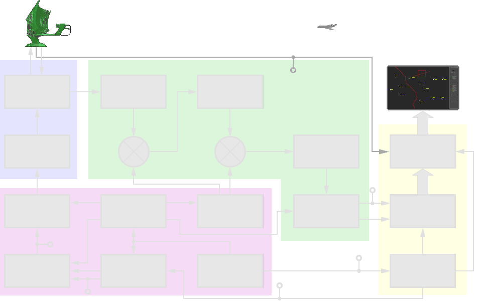
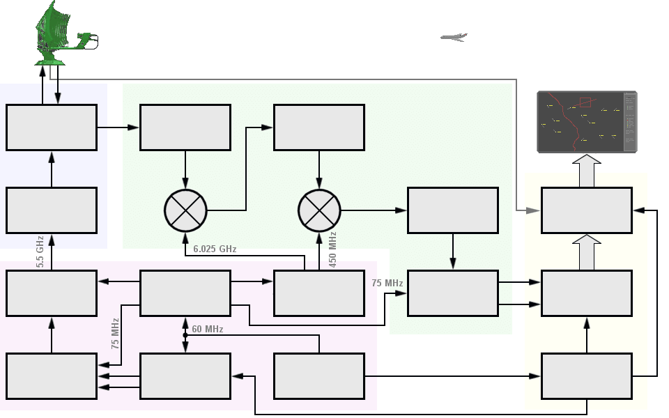
Figure 1: a simplified block diagram of a fully coherent radar.

Preamplifier
Amplifier
Amplifier
Amplifier
Processor
Synthesizer
Detector
Converter
Generator
Oscillator
Control
Figure 1: a simplified block diagram of a fully coherent radar.

Preamplifier
Amplifier
Figure 1: a simplified block diagram of a fully coherent radar. (interactive picture)
Fully Coherent Radar
At a fully coherent radar all the necessary clocks, pulses, gates and frequencies are derived from the highly stable oscillation of a master oscillator and are synchronous with its oscillation. All derivative frequencies have a fixed phase relationship to this one master oscillator.
The block diagram on the figure illustrates the principle of a fully coherent radar. The fundamental feature is that all signals are derived at low level and the output device serves only as an amplifier. All the signals are generated by one master timing source, usually a synthesiser, which provides the optimum phase coherence for the whole system. The output device would typically be a klystron, TWT or solid-state. Fully coherent radars exhibit none of the drawbacks of the pseudo-coherent radars, which we studied in the previous section.
The color deposited assemblies are often grouped together. For example, here to transmitter (blue), receiver (green), signal generator (pink) and radar signal processing (ocher). However, the individual sub-assemblies can be assigned to different parent assemblies (depending on the manufacturer).
The term coherence has thus in radars a feature that is very different from the considerations in optics. In optics is often spoken by a coherence length. Only within the coherence length, interference is possible. In fully coherent radars this coherence length is practically endless: the master oscillator can be compared to a continuously oscillating dipole here. From this constant oscillation only a small section is always cut and then used as a transmission pulse. Unwanted phase jumps and polarity changes are not possible within the transmitter. For example, in a satellite radar all echo signals (from the same distance) are coherent with each other, and are also coherent with the transmission frequency, regardless of whether they come from different pulse periods; and even regardless of whether they originate from a previous Earth orbit.
Functional Characteristics
Duplexer
The duplexer alternately switches the antenna between the transmitter and receiver so that only one antenna need be used. This switching is necessary because the high-power pulses of the transmitter would destroy the receiver if energy were allowed to enter the receiver.
Low Noise Preamplifier
The Low-Noise Preamplifier (LNA) amplifies the very weak backscatter signals. The low noise characteristic is very important: all following amplifiers will amplify the added noise of the LNA! The amplifier has a gain of 18...25 dB. A higher gain would be possible but this decreases the dynamic of the receiver.
Mixer Stage
The function of the mixer stage is to convert the received rf energy to a lower, intermediate frequency (IF) that is easier to amplify and manipulate electronically. The intermediate frequency is usually 30 or 60 megahertz. It is obtained by heterodyning the received signal with a local-oscillator signal in the mixer stage. The mixer stage converts the received signal to the lower IF signal without distorting the data on the received signal.
IF-Amplifier
After conversion to the intermediate frequency, the signal is amplified in several IF-amplifier stages. Most of the gain of the receiver is developed in the IF-amplifier stages. The first IF- amplifier has got a wide bandwidth and suppress the influence of mirror-frequencies. The center frequency is relatively high, up to 450 MHz nominally. The overall bandwidth of the receiver is often determined by the bandwidth of the stages of the second IF amplifier. The center frequency is about 75 MHz nominally.
Power Amplifier
In this system the transmitting pulse is caused with a small performance in a waveform generator. It is taken to the necessary power with a Power Amplifier followingly. The Power Amplifier would typically be a klystron, Traveling Wave Tube (TWT) or solid-state.
Mixer / Exciter
The first stage of cascaded mixers. The function of this mixer stage is to modulate a prospective intermediate frequency (IF) with the transmitting signals waveforms. The I- (in-phase) and Q- (quadrature) signals from the Waveform Generator are defined signals for comparing with the backscatter in the receivers synchronous detector.
Waveform-Generator
The Waveform-Generator generates the transmitting pulse in low- power. It generates the transmitting signal on an IF- frequency. It permits generating predefined waveforms by driving the amplitudes and phase shifts of carried microwave signals. These signals may have a complex structure for a pulse compression.
Phase Sensitive Detector
The IF-signal is passed to a phase sensitive detector which converts the signal to base band, while faithfully retaining the full phase and quadrature information (I & Q- processing) of the Doppler signal.
Radar Signal Processor
The signal processor is that part of the system which separates targets from clutter on the basis of Doppler content and amplitude characteristics. It generates plots and tracks from the videosignals of the receiver.
Radarscope / Monitor
The indicator presents to the observer a continuous, easily understandable, graphic picture of the position of radar targets. In recently radars the indicator would be a computerdisplay.
