Digital Raster-Scan Monitor
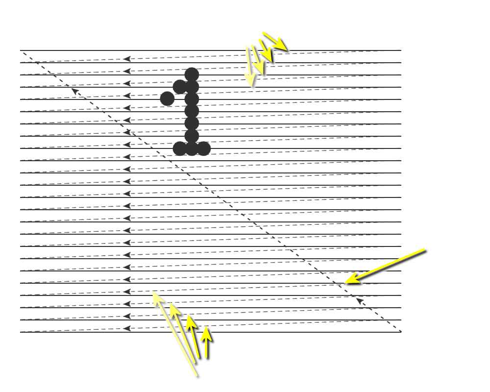
Figure 1: Principle of image structure in a raster scan monitor
Digital Raster-Scan Monitor
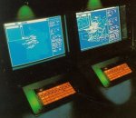
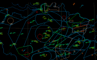
All informations are shown on a digital raster-scan monitor. The polar coordinate information of the targets' positions is converted to rectangular coordinates for registration with the digitally stored surface maps and for display.
Functionality
The entire screen is divided into a system of lines of dots. In cathode ray tubes, which were used earlier, the electron beam had to sweep all these dots in succession. The size of these dots (pixels) was dependent on the video bandwidth in a cathode ray tube systems. In the image had to be organized a horizontal and a vertical retrace.
- Horizontal retrace: The return to the left of the screen, after refreshing each scan line.
- Vertical retrace: At the end of each frame the electron beam returns to the top left corner of the screen to begin the next frame.
During these retrace periods of the electron beam was blanked (Blanking Retrace Period). The quality of a raster image is determined by the total number pixels (resolution), and the amount of information in each pixel (color depth). Newer semiconductor screens use for reasons of time, a similar system. However, an organization of a horizontal and a vertical retrace is not necessary here, since random access is possible to the frame buffer.
Application as radar screen
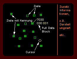
Raster scan monitors for radars should have highest possible resolution. These are usually also used to display important radar parameters and control buttons for the radar device. A target can be be marked with help of a cursor and then additional information about this target will be displayed on the screen. A permanent display of all additional information may also be chosen but this is too confusing for heavy traffic.
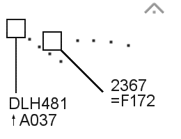
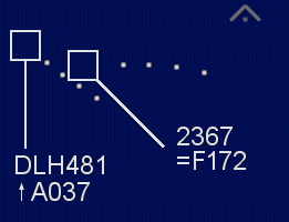
In an air traffic control radar the symbolism may look like shown in Figure 4 down in the gallery. Here, the square is the symbol for the position of an aircraft, which is guided only with the primary radar. If the square is filled with a cross, then this symbol marks a target which is controlled with both the primary and the secondary radar. The cross marks a target provided by secondary radar only. The points represent a target history, i.e. this were the positions of the target in previous revolutions of the antenna. The upper character string is the identification number of the aircraft. The bottom character string is the height either as flight level, or at low altitudes as barometric altitude.
Addition to the presentation of symbols and alphanumeric characters is also possible to choose a form of representation of the raw video (like as for analog PPI-scope). That is, depending on the display a two-dimensional area of false color or grayscale that simulates a brightness modulation. This form of representation is called Skin Paint Mode
The raster scan monitor has a distinct advantage: besides the possibility of presenting a large number information of, its presentation can also be seen in daylight without restrictions. (The brightness modulated representations of weak targets on an analog PPI-scope are visible only in a darkened environment.) The approach control room of an aerodrome no longer needs to be a creepy dark room, it can now be a normal friendly bright office.

