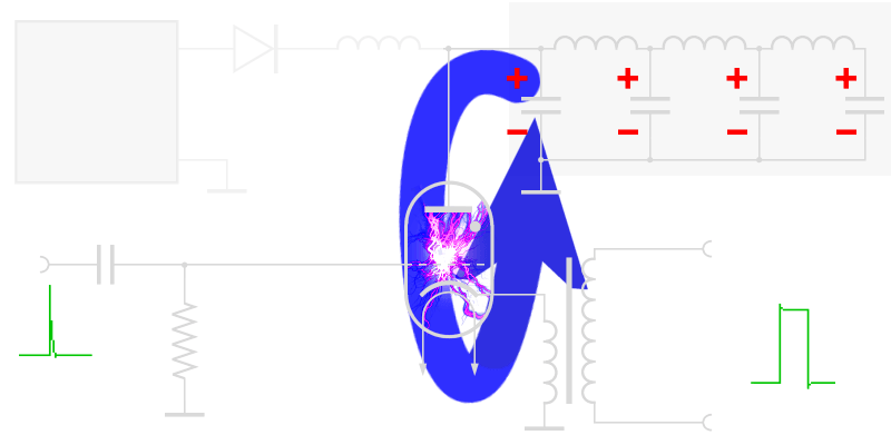
Radar Modulator
Radio frequency energy in radar is transmitted in short pulses with time durations that may vary from 1 to 50 microseconds or more. In order to generate this short pulse of high power, a special modulator is required which generates a high voltage for the transmitter tube at the moment of transmission. This radar modulator switches on the anode voltage for the high power tube for the duration of the pulse. Therefore it is sometimes called "keyed on/off" radar modulator.
However, high power amplifiers using cross field amplifiers (amplitron) also require such a radar modulator, as they may only get the anode voltage for the duration of the transmission pulse.
power supply
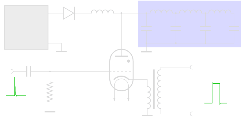
Figure 1: Thyratron Modulator
power supply
Figure 1: Thyratron Modulator
power supply
Figure 1: Thyratron Modulator (interactive picture)
This modulator uses a pulse-forming network for energy storage. This pulse-forming network is charged to twice the voltage of the high-voltage power supply unit during charging using the magnetic field of the charging coil. This charging coil simultaneously limits the charging current. A charging diode is inserted so that the pulse-forming network is not discharged via the internal resistance of the power supply after charging.
The hydrogen thyratron operates as an electronic switch and is controlled by a short trigger. The R-C combination separates the thyratron input from the preamplifier's bias voltage. The pulse transformer is used to adjust the impedances during the discharging.
As a circuit for storing energy, the thyratron modulator uses essentially a short section of artificial transmission line which is known as the pulse-forming network (PFN). Via the charging path, this PFN is charged on the double voltage of the high voltage power supply with help of the magnetic field of the charging impedance. Simultaneously this charging impedance limits the charging current. The charging diode prevents that the PFN discharge himself about the intrinsic resistance of the power supply again.
The function of thyratron is to act as an electronic switch which requires a positive trigger of only 150 volts. The thyratron requires a sharp leading edge for a trigger pulse and depends on a sudden drop in anode voltage (controlled by the pulse-forming network) to terminate the pulse and cut off the tube. The R-C Combination acts as a DC- shield and protects the grid of the thyratron. This trigger pulse initiates the ionization of the complete thyratron by the charging voltage. This ionization allows conduction from the charged pulse-forming network through the pulse transformer. The output pulse is then applied to a self-oscillating stage, such as a magnetron.
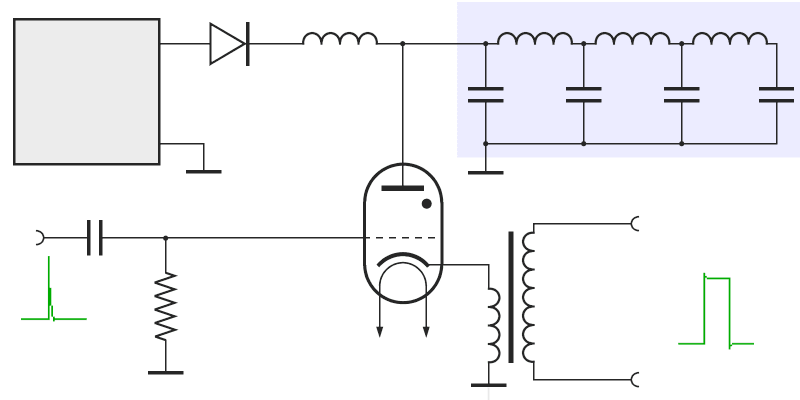
Figure 2: Keyed on/off modulator of the Russian VHF-radar P-18 “Spoon Rest D”, using a thyratron.
voltage
power
supply
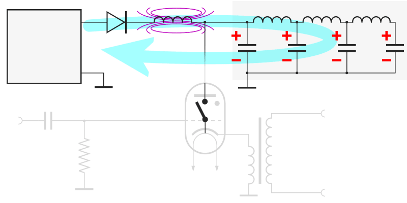
Figure 3: charging currents path
power supply
Figure 3: charging currents path
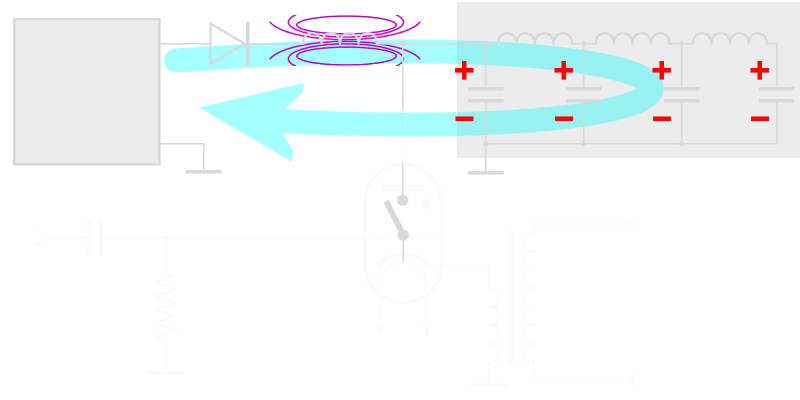
The Charge Path
As an initial condition is assumed that the circuit is not energized. In the figure, the thyratron is shown as an open switch.
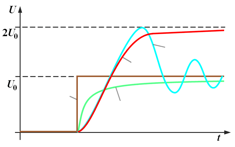
Once the power supply is switched on (look at the brown voltage jump in the right diagram), the current flows through the charging diode and the charging coil and charges the capacitors of the pulse-forming network (PFN). The coils of the PFN are not yet functional (having too small inductivity). However, the induction of the charging impedance offers high inductive resistance to the current and builds up a strong magnetic field. The charging of the capacitors follows an exponential function (line drawing green). The self-induction of the charging coil overlaps for this.
of the power
supply)
a capacitor
without charging
diode
Figure 4: diagram of charging currents
of the power
supply)
a capacitor
without charging
diode
Figure 4: diagram of charging currents
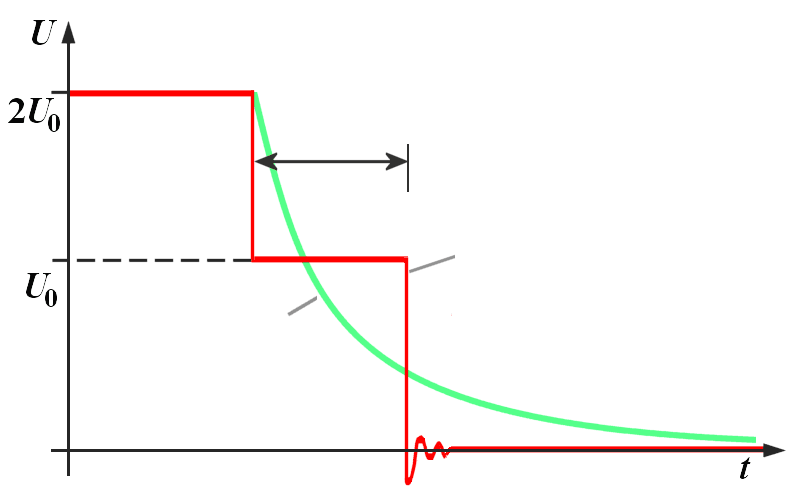
| UC = U0 · (1 - cosωr · t) | ||
| ωr2= | 1 | (1) |
| LDr · ΣC | ||
If the capacitors are charged with the power supplies voltage, decreases the current and the magnetic field breaks down. The breaking down magnetic field causes an additional induction of a voltage. This one continues the charging of the capacitors up to the double voltage of the power supply. Now the capacitors would be discharged (blue curve) about the power supplies resistance but the charging diode cut off this current direction and the energy remains stored therefore in the capacitors.
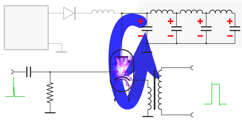
The Discharging Path
(fired)
Figure 5: discharging currents path
(fired)
Figure 5: discharging currents path
When a positive trigger pulse is applied to the grid of the thyratron, the tube ionizes causing the pulse-forming network to discharge through the thyratron and the primary of the pulse transformer. (The thyratron is “fired”.)
The fired thyratron grounds the pulse line at the charging coil and the charging diode effectively. Therefore, a current flows for the duration τ through the pulse transformer primary coil to ground and from ground through the thyratron, which is now conducting to the other side of the pulse forming network. The high voltage pulse for the transmitting tube can be taken on the secondary coil of the pulse transformer. Exactly for this time an oscillating device swings on the transmit frequency. Because of the inductive properties of the PFN, the positive discharge voltage has a tendency to swing negative.
If the oscillator and pulse transformer circuit impedance is properly matched to the line impedance, the voltage pulse that appears across the transformer primary equals one-half the voltage to which the line was initially charged.
capacitor
pulse-forming network
Figure 6: diagram of discharging currents
capacitor
pulse-forming network
Figure 6: diagram of discharging currents