Transponder
Transponder
Secondary radar depends on a transponder (short-for Transmitter-responder) in the airplane to respond to interrogations from the ground station to make the aircraft visible and to report additional information like the aircraft's altitude.
Figure 1 shows an older one transponder. The replays code for Mode 1 and 3/A can be choosen with the black hand wheels. The yellow painted edges mark this device as reference unit of a repair shop.
Newer one transponders operate with two antennae and two receivers in diversity mode. One antenna is mounted on top and the other one at the bottom of the airplanes fuselage. Additional informations are derived from the onboard avionics navigation systems.

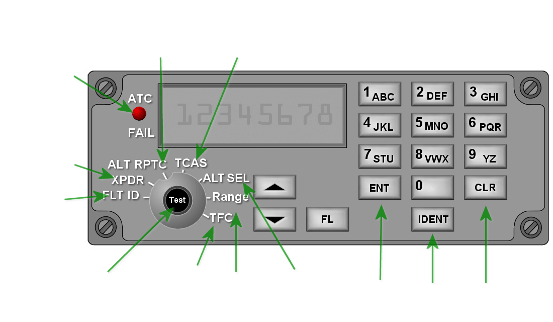
(basically enabling
Mode C)
selected, TAs and
RAs are provided
Failure
Indicator
Mode A
Code
Flight ID
(press)
(Auto or
Manual)
Range
Altitude (not
selected Alt)
(Enter)
Figure 2: Possible view of a main display of a Mode-s transponder

(basically enabling
Mode C)
selected, TAs and
RAs are provided
Failure
Indicator
Mode A
Code
Flight ID
(press)
(Auto or
Manual)
Range
Altitude (not
selected Alt)
(Enter)
Figure 2: Possible view of a main display of a Mode-s transponder
The Transponder maintains avionics data in 256 different 56 bit wide Binary Data Store (BDS) Registers that can be loaded with information and read-out by the ground system. Each register contains the data payload of a particular Mode S reply or extended squitter. These BDS registers are also referred to as Ground Initiated Comm B (GICB) registers. They are specified in the ICAO document “Manual on Mode S Specific Services” (Doc 9688). Registers not updated within a fixed period are cleared by the transponder. Registers are identified by a two digit hex number for example BDS 05h (in some publications written as BDS 0,5) is the position squitter. Commonly used registers are shown in Table 1.
| Register | Content |
|---|---|
| BDS 01h | Data Link Capability Report |
| BDS 02h | Aircraft Identity |
| BDS 03h | ACAS Resolution Advisory |
| BDS 04h | Selected Vertical Intent parameters (Bit 28…40: Barometric Pressure Setting) |
| BDS 05h | Extended Squitter Airborne Position |
| BDS 06h | Extended Squitter Surface Position |
| BDS 07h | Extended Squitter Status (transmitted only in reply to interrogation) |
| BDS 08h | Extended Squitter A/C Id & Category |
| BDS 09h | Extended Squitter Airborne Velocity |
| BDS 0Ah | Extended Squitter Event Report |
| BDS 61h | Extended Squitter Emergency/Priority Status (transmitted once per second during an emergency) |
| BDS 65h | Aircraft Operational Status |
Tabelle 1: Content of some binary data store registers

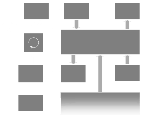
converter
converter
amplifier
generator
oscillator
Figure 3: Functional Block Diagram of a modern transponder

converter
converter
amplifier
generator
oscillator
Figure 3: Functional Block Diagram of a modern transponder

converter
converter
amplifier
generator
oscillator
Figure 3: Functional Block Diagram of a modern transponder

