Frequency-Modulated Interrupted Continuous-Wave Radar (FMiCW Radar)
switch
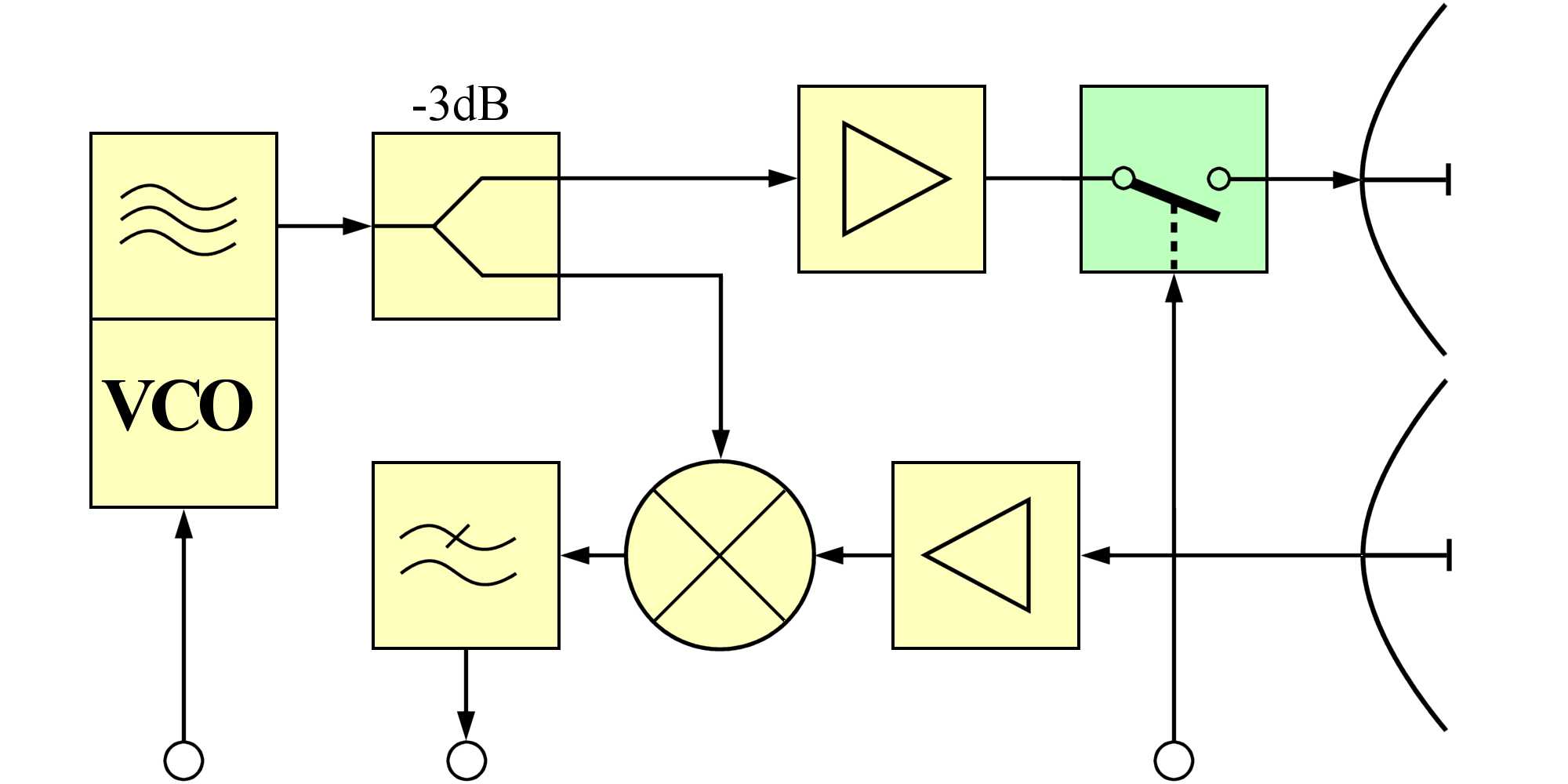
Figure 1: FMiCW radar uses an additional PIN diode switch to turn off the transmitter power.

switch
Figure 1: FMiCW radar uses an additional PIN diode switch to turn off the transmitter power. (interactive picture)
Frequency-Modulated Interrupted Continuous-Wave Radar (FMiCW Radar)

Schalter
Figure 1: FMICW radar uses an additional PIN diode switch to turn off the transmitter power during the measuement.
Frequency Modulated interrupted Continuous Wave, FMiCW - Radar or also-called iFMCW- Radar, radar gets a special position within the radar technologies. During the measuring process, the transmit signal is switched off temporarily. Formally, the radar is thus a pulse radar. During the shutdown of the transmitting antenna, the frequency generation in the transmitter, however, continues to operate and provides the receiver with the necessary for downconversion frequency. The measuring process for determining the distance is a measure of the frequency difference between the actual transmitter frequency and the carrier frequency of the echo signals as in an FMCW radar. So it is not a pure runtime measurement similar to a pulse radar with intra-pulse modulation.
Pulse-shaped amplitude modulation of the transmitted signal
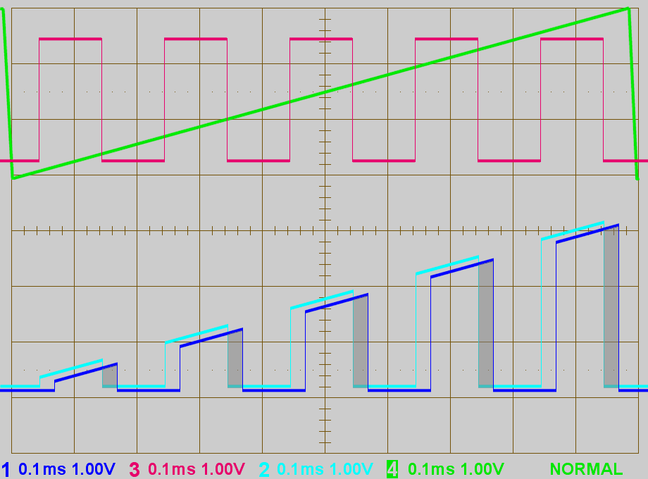
Figure 2: Oscillograms for the block diagram
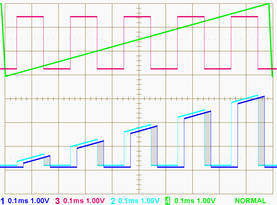
Figure 2: Oscillograms for the block diagram

Figure 2: Oscillograms for the block diagram
Compared with the pure FMCW radar the FMICW radar has advantages and disadvantages. Normally the transmit signal will leak into the receiver directly at an FMCW-radar. At an FMiCW radar, the isolation between the transmitter and the receiver is improved by a temporary disconnection of the transmission power. During the time in which the antenna does not radiate, the receiver can be made much more sensitive. This would also allow a higher transmission power. Both measures together can increase the maximum range of the radar.
However, turning off the receiver during the transmission time (for example, by the inverted control voltage for the PIN diodes) reduces the time window in which an echo signal can be received. Any echo signals (in Figure 2 the blue channel) can only be received, if the control voltage has a low level (in Figure 2 the red channel). In Figure 2, this difference in time between the echo signal and the control voltage is colored in gray. This is often only a very short time. This means that the possibilities deteriorate for non-coherent signal integration. It can be received a small portion of the echo signal only. This reduces the energetic content of the received echo signals and consequently the maximum range of the radar. Echo signals from the close range have a bigger disadvantage than echo signals from larger distances. The effect is similar to the sensitive time control (STC) in a pulse radar.
This kind of FMiCW radar is used for example in modern automotive radars (adaptive cruise control) in the frequency band 76 – 77 GHz. Each of the sub-pulses can be emitted in a slightly different side angle by switching the feed points of a patch antenna array for azimuth determination.
FMiCW radar as a measuring range extension
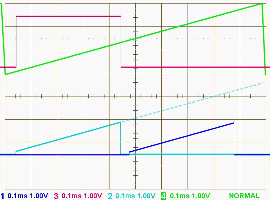
Figure 3: Oszillogramms for the block diagram

Figure 3: Oszillogramms for the block diagram
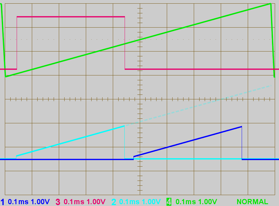
Figure 3: Oszillogramms for the block diagram
As another solution, the methodology can be used to better exploiting the allowable transmitter bandwidth. The higher steepness of the frequency change then allows a higher resolution while maintaining the maximum possible range.
In an FMCW radar in the ISM band (Industrial, Scientific and Medical Band) 24 GHz, the transmitter shall work only from 24.0 to 24.25 GHz. When using this transmitter bandwidth, a compromise must be found between resolution and maximum range of the radar.
Using the FMICW radar method, the steepness of the change in frequency can be adjusted so that the transmitter, for example, has twice the bandwidth, therefore it operates from 24.0 to 24.5 GHz. When reaching the upper border of the ISM-Band (24.25 GHz), the transmitter signal is then switched off from the antenna: it will be emitted the allowed frequency range only. The echo signal can now have a much larger runtime than the duration of the radiated transmit signal. It is then compared with the much larger internal sawtooth (in Figure 3 the dashed extension of the transmitted signal).
