Klystron
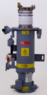
Figure 1: Klystron Type NSN 662-5861 of English Electric Valve Co Ltd.
(Courtesy of OSTRON)
What is a klystron?
Klystron
Klystrons are high power microwave vacuum tubes. They are velocity-modulated tubes that are used in radars as amplifiers or oscillators. A klystron uses the kinetic energy of an electron beam for the amplification of a high-frequency signal. Klystrons make use of the transit-time effect by varying the velocity of an electron beam. It is a linear beam device; that is, the electron flow is in a straight line focused by an axial magnetic field. The magnetic field is only used to focalize the electron beam. A klystron has one or more special cavities around the axis of the tube that modulate the electric field. Due to the number of the resonant cavities, klystrons are divided up into two-cavity klystrons, multi-cavity klystrons, and repeller klystrons.
The gain of klystron amplifiers can be very high (more than 60 dB), with output power up to tens of megawatts. But klystrons have limited bandwidth (less than 2%) because of their use of resonant cavities. They require high supply voltages in the region of hundreds of kilovolts. As to be expected with vacuum tubes, they have fewer reliabilities from 5000 to 75000 hours of the mean time between failure.
Two-Cavity Klystron
The two-cavity klystron is a widely used microwave amplifier operated by the principles of velocity and density modulation. An electronic oscillator can also be made from a klystron tube when the second cavity resonator is fed back to the first one with a coaxial cable or waveguide. This connection must have a defined delay so that the oscillations are in phase. However, a two-cavity klystron oscillator is inappropriate in the structure, because, when the oscillation frequency is varied, the resonant frequency of each cavity and the feedback path phase shift must be mechanically readjusted for positive feedback. (A repeller klystron is better suited for such cases.)
Design
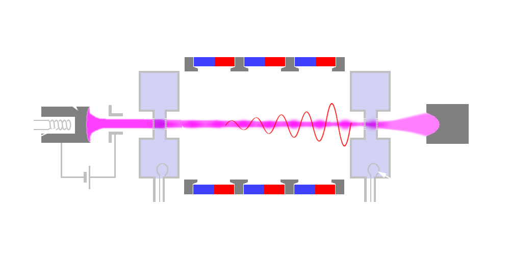
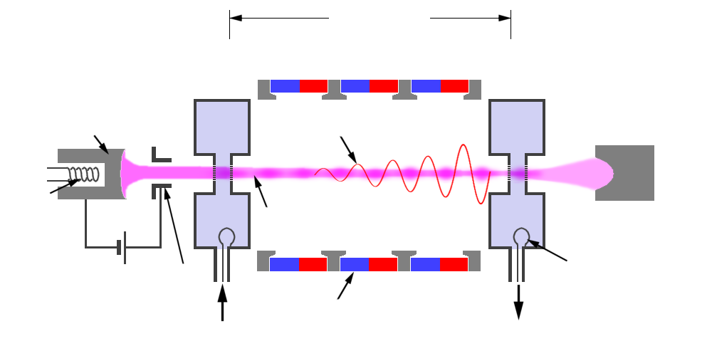
A klystron size is determined by the size of the bunching cavities. The physical components of a two-cavity klystron consist of an electron emitter, two resonant cavities, a solenoid magnetic circuit to focuses the electron beam, and a collector depression structure. In order to achieve high powers, this electron emitter must emit a large number of electrons. A two-cavity klystron uses two resonant cavities around the axis of the tube which modulates the electric field. In the middle of these cavities, there is a grid allowing the electrons to pass. The first cavity with the first coupling device is called the “buncher”, while the second cavity with its coupling device is called the “catcher”. The area beyond the buncher grids is called the “drift space”. The collector collects the energy of the electron beam and changes it into heat.
The collector is clamped to ground potential. A so-called beam voltage of up to several hundred kilovolts is applied between the cathode and the collector, which is why the collector generates X-ray interferences and must be shielded with lead.
cavity
cavity
loop
Figure 2: mode of operation of a two-cavity klystron
cavity
cavity
loop
Figure 2: mode of operation of a two-cavity klystron

cavity
cavity
loop
Figure 2: mode of operation of a two-cavity klystron
(interactive picture)
Function
The electrons injected from the cathode are first accelerated by the high DC voltage before entering the buncher grids and arrive at the buncher with uniform velocity. The signal present in the buncher generates an additional local electric field. The direction of the electric field changes with the frequency of the signal into the buncher. These changes alternately accelerate and decelerate the electrons of the beam passing through the grids. The electrons that pass through the first cavity at zero points of the signal voltage pass through with unchanged velocity; those that pass through the positive half cycles of the signal voltage undergo an increase in velocity; those passing through the negative swings of the signal voltage undergo a decrease in velocity. The variation of the electron velocity in the drift space is called velocity modulation. The faster electrons catch up with the slower electrons and form bunches. The electron beam is spatially modulated then.
The function of the catcher cavity is to absorb energy from the electron beam. The catcher grids are placed along the beam at a point where the bunches are fully formed. The location is determined by the transit time of the bunches at the natural resonant frequency of the cavities (the resonant frequency of the catcher cavity is the same as the buncher cavity). The electrons then leave the catcher at a reduced speed and reach the collector.
Characteristics
The efficiency of klystron results from the ratio of the power supplied to the klystron (as a DC-power supply) and the high-frequency power output. The efficiency of a two-cavity klystron is about 40%. Losses occur primarily due to a non-ideal bundling of the electron density and the remaining energy of the electrons, which is converted into heat in the collector. The average output power is up to 500 kW and pulsed power is up to 30 MW at 10 GHz. The power amplification is up to 30 dB.
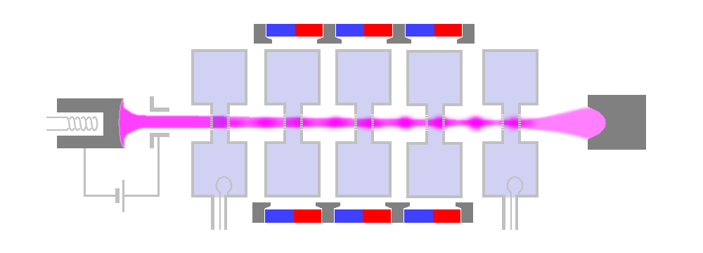
Figure 3: Structure of a multicavity klystron
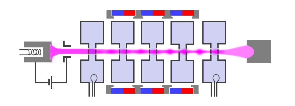
Figure 3: Structure of a multicavity klystron
Multicavity Power Klystron
Klystron amplification, power output, and efficiency can be greatly improved by the addition of intermediate cavities between the input and output cavities of the basic klystron. These additional cavities are also referred to as “Gain-Cavities”. They serve to velocity-modulate the electron beam and produce an increase in the energy available at the output. The electron bunches getting strengthened. The multicavity klystrons may be used to increase the gain of the klystron or to increase the bandwidth. They are often operated with their cavities stagger-tuned so as to obtain a greater bandwidth of up to 8% at a reduction in gain.
A new concept of multi-chamber klystrons is called kladistron (derived from adiabatic klystron). Kladistrons are high-performance klystrons with a large number of cavities (at least twice as many as with conventional klystrons). Kladistrons are not used in radar sets.
Figure 4: Cutaway view of an MBK using 8 electron guns made by TESLA
Multi-beam Klystron
Multi-beam klystrons (MBK) are klystrons with multiple electron beams, simply put, a number of single beam klystrons in parallel with common input and output cavities. Their other cavities and focusing systems can either be common or separate. Multi-beam klystrons are capable of delivering immense amounts of microwave power at lower beam voltages (typically 50 to 80%). This also leads to a shorter circuit length (typically 30 to 60%), as the electrons have a slower average speed. Another advantage of multi-beam klystrons is that they have much wider bandwidth. Multi-beam klystrons are either focused with magnetic fields, or with electrostatic focusing.
Multi-beam klystrons achieve an efficiency of 60 to 80%. They are commonly used for accelerator applications. (In connection with the term multi-beam klystron, the klystrons with one beam only are called mono-beam klystron.)
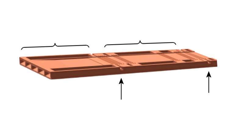
Figure 5: Half shell milled into a continuous casting for a Sheet-beam Klystron
Figure 5: Half shell milled into a continuous casting sheet for a Sheet-beam Klystron
Sheet-beam Klystron
In the klystrons considered so far, the cross-section of the electron beam was round. They are also referred to as pencil-beam tubes. In a sheet-beam klystron, the electron beam is flat. This is achieved by a special shape of the electron gun.
Sheet beam klystrons have beams of much lower current density. Since their cathode loading is much lighter, they can be expected to have a much longer life as well. They can also be constructed as Multi beam Klystron, e.g. by arranging two beams on top of each other to a Double Sheet-Beam Klystron (DSBK).
The fabrication of a sheet-beam klystron is much simpler and requires considerably fewer parts. All cavity resonators, the drift space, and the collector are integrated (for example by milling) into a flat rod made of solid material. This rod and a mirrored rod are placed on top of each other. This creates the complete resonance structure of the sheet-beam klystron. Much more effective cooling is possible than available in the pencil-beam tube.
Repeller Klystron
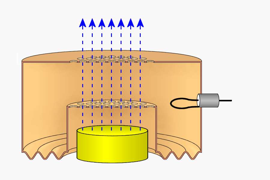
with pickup loop
cavity
through holes
Figure 6: Cavity resonator of the repeller klystron
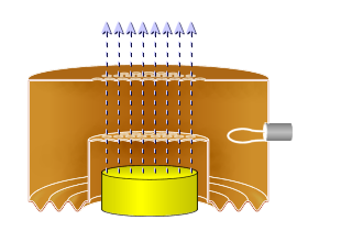
with pickup loop
cavity
through holes
Figure 6: Cavity resonator of the repeller klystron
Another tube based on velocity modulation, and used to generate microwave energy, is the reflex klystron (repeller klystron). The reflex klystron contains a reflector plate, referred to as the repeller, instead of the output cavity used in other types of klystrons. The electron beam is modulated as it was in the other types of klystrons by passing it through an oscillating resonant cavity but here the similarity ends. The feedback required to maintain oscillations within the cavity is obtained by reversing the beam and sending it back through the cavity. The electrons in the beam are velocity-modulated before the beam passes through the cavity the second time and will give up the energy required to maintain oscillations. The electron beam is turned around by a negatively charged electrode that repels the beam (“repeller”). This type of klystron oscillator is called a reflex klystron because of the reflex action of the electron beam.
The cavity resonator must be flexible on at least one wall due to the tolerances of the tube manufacturer. There are no two identical reflex klystrons, even if they are manufactured in the same series. Each reflex klystron, therefore, has its own calibration protocol.
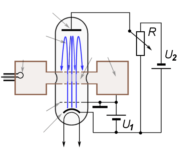
grid
room
cavity
Figure 7: circuit diagram with a repeller klystron
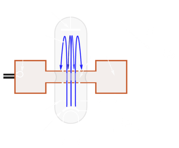
grid
room
cavity
Figure 7: circuit diagram with a repeller klystron
Three power sources are required for reflex klystron operation:
- filament power,
- positive resonator voltage (often referred to as beam voltage) used to accelerate the electrons through the grid gap of the resonant cavity, and
- negative repeller voltage used to turn the electron beam back.
The electrons are focused into a beam by the electrostatic fields set up by the resonator potential (U2) in the tube.
The reflector voltage must be adjusted so that the bunching is at a maximum as the electron beam re-enters the resonant cavity, thus ensuring a maximum of energy is transferred from the electron beam to the RF oscillations in the cavity. The voltage may be varied slightly from the optimum value, which results in a slightly variation in frequency (about 1 percent), but also in loss of output power.
Applications
Figure 8: Repeller klystron K-806

Figure 8: Repeller klystron K-806
Klystrons have a wide range of applications in high-frequency technology, as the performance achievable with klystrons cannot be achieved with semiconductor components. Therefore, the low reliability of vacuum tubes is accepted.
- Klystrons are used in weather radars, as the use of intrapulse modulated transmitters is problematic there.
- Klystrons are used in accelerators in research. Elementary particles can be accelerated with the help of high-frequency electromagnetic fields. However, this requires huge high-frequency powers of the order of 250 klystrons, each of them operates in the megawatt range. These klystrons operate in the frequency range from about 200 MHz (which requires quite large resonators) to the S and X-Bands.
- large klystrons are used in terrestrial television transmitters in the UHF range.
- smaller repeller klystrons (as shown in Figure 8) have been used as stable local oscillators in measuring amplifiers and receivers because they can be easily tuned in frequency in a small range.
- Applications of W-Band klystrons are currently the subject of laboratory research. The high precision of cavity resonators in the range of 2 to 3 microns requires new manufacturing processes that are otherwise used in the semiconductor industry. This process is called LIGA and is a combination of deep-etch lithography and electroforming.
