Cavity Resonators

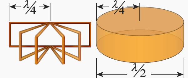
Figure 1: cylindrical resonant cavity beeing formed from quarter-wave sections
Cavity Resonators
Cavity resonators replace conventional oscillating circuits at high frequencies. They have the necessary quality Q to create narrowband filters in these frequency ranges (very small capacitance, very small inductance). Resonant cavities have a very high Q and can be built to handle relatively large amounts of power. Cavities with a Q value in excess of 30,000 are not uncommon.
The high Q gives these devices a narrow bandpass and allows very accurate tuning. Simple, rugged construction is an additional advantage.
The Figure shows the development of a cylindrical resonant cavity from an infinite number of short-circuited quarter-wave sections of transmission line.
Resonant cavities are widely used in the microwave range. For example, most microwave tubes like klystrons and Traveling Wave Tubes use cavities in different shapes to generate microwave energy.

with pickup loop
cavity
through holes
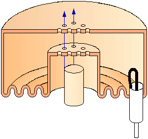
Figure 2: Resonant cavity of a repeller klystron

with pickup loop
cavity
through holes
Figure 2: Resonant cavity of a repeller klystron
Several cavity shapes are commonly used: cube, cylinder, sphere, „doghnut”-shaped and so on. E.g. Figure 2 shows the cavity of a repeller-klystron, a cylindrical ring.
There are two variables that determine the primary frequency of any resonant cavity. The first variable is physical size. In general, the smaller the cavity, the higher its resonant frequency. The second controlling factor is the shape of the cavity. The resonant frequency of a cavity can be varied by changing any of three parameters: cavity volume, cavity capacitance, or cavity inductance. Changing the frequencies of a cavity is known as “Tuning”.

