In-phase & Quadrature Procedure
Figure 1: Real and imagine quantities
If already the IF-frequency with a fast but simple A/D-Converter is digitized, then I have a digital amplitude value for every rangecell. This one represents the real part of the complex echo signal but where does the phase information remain? Yes, with the simple method the phase information is lost!
Synchronous Detector
A complex quantity always consists of a real part (light green) and an imaginary part (light blue). However, an analog/digital converter always will take only the real part lying in the X-axis into account.
This is no problem by older radars. The blip is composed of a minimum of 12 to 15 pulses. If one or two pulses have the real amplitude of zero (by maximum of phase shift), the blip is visibly anyway. But the newer radars use a so-called Monopulse Technology often. All data are a result of one transmitted pulse only. So we need the imagine data too!
Sychronous detector provides a representation of the IF signal, including phase and amplitude without loss of information. The baseband in-phase (I) and quadrature-phase (Q) signals are digitized using a pair of A/D converters The synchronous detector is also referred to as a quadrature channel receiver, quadrature detector, I/Q demodulator, or coherent detector.
Well, If I turn the whole construct by 90° ...
then the former imaginary part then is exactly on the X-axis and can be digitized but the former real part is dropped now!
But the amount of the original vector can be calculated again with help of the theorem of Pythagoras from these two results.
And how turns one the whole construct by 90° now?
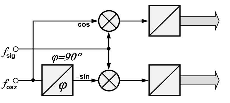
Figure 2: Block diagram of synchronous detector

Figure 3: a concrete example (Dokumentation)
Oh, this is quite simple: the phase of the signal must be moved by 90°. Both analogous parts of the signal then must be digitized. Now I have but twice so many data lines but the digital processor controlled signal processing primarily brings me very much more possibilities for this.
The resulting digital data can then be processed using a wide variety of digital signal-processing algorithms.
(Digital filters have for example very much steeper edges than analogous constructions ...
... by the very early conversion into digital signals neither noise can distort my data
from the following signal way... and so on)
The I and Q components are related as
| I = A cos(Φ) Q = A sin(Φ) |
(1) |
From this, the signal magnitude A and phasen angle Φ can be calculated as
| A2= I2+Q2 Φ=arctan(Q/I) |
(2) |
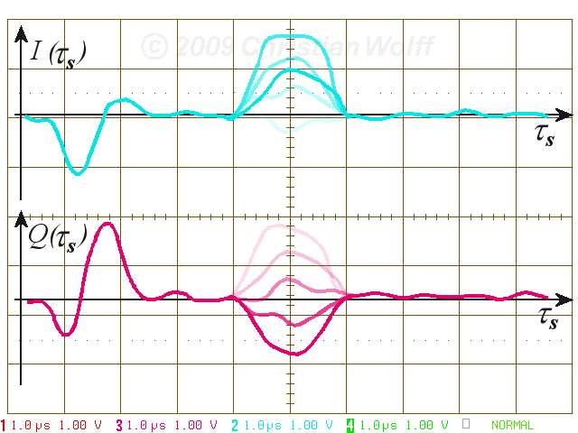
Figure 3: In-Phase-signal (cyan) and Quadrature-signal (magenta)