Detector

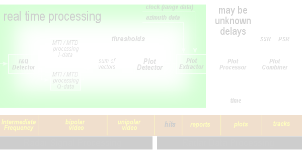
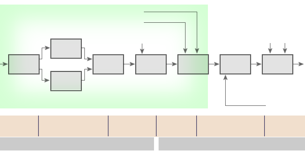
Figure 1: Part of the block diagram (information flow)

Detector
I-channel
Q-channel
algorithm
Detector
Extractor
Processor
Combiner
SSR and PSR
Sources
frequency
video
video
Figure 1: Part of the block diagram (information flow)

Detector
I-channel
Q-channel
algorithm
Detector
Extractor
Processor
Combiner
SSR and PSR
Sources
frequency
video
video
Figure 1: Part of the block diagram (information flow)
Detector
The output of the receiver is a signal, which contains the required target plus various forms of noise and clutter. In the case of the MTI output, this clutter residue is the result of imperfect cancellation due to various factors such as equipment instability, antenna modulation, lack of dynamic range or Doppler content within the clutter itself. The detection process separates the required target from the noise and clutter. Detectors are normally designed to carry out this process with a constant false alarm rate (CFAR).
The diagram shows the location of the detector in the chain of signal processing. This device forms the information on a point like target as a digital report. The up to this point existing information about the analog value (or digital description of) of the received power in a particular binary cell will be be transformed to information about the coordinates of a target. The value of the power is included in this report mostly.
The important procedure is, that up to this point all binary cells (containing the received power) must be processed. After the detector exist only reports about selected binary cells. However, there may exist several reports about a single target, generated by adjacent binary cells. This will processed in the next device.
