Phased Array Antenna
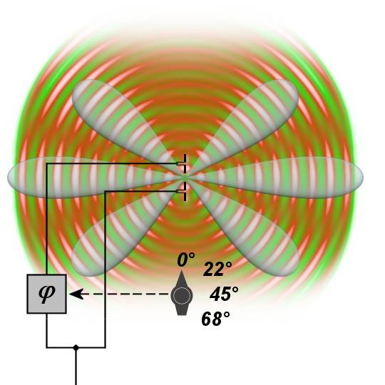
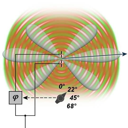
Figure 1: left:two antenna elements, fed with the same phase, right: two antenna elements, fed with different phase shift
Figure 1: left:two antenna elements, fed with the same phase, right: two antenna elements, fed with different phase shift
Phased Array Antenna
A phased array antenna is composed of lots of radiating elements each with a
phase shifter.
Beams are formed by shifting the phase of the signal emitted from each
radiating element, to provide constructive/destructive
interference
so as to steer the beams in the desired direction.
In the figure 1 (left) both radiating elements are fed with the same phase. The signal
is amplified by constructive interference in the main direction. The beam sharpness
is improved by the destructive interference.
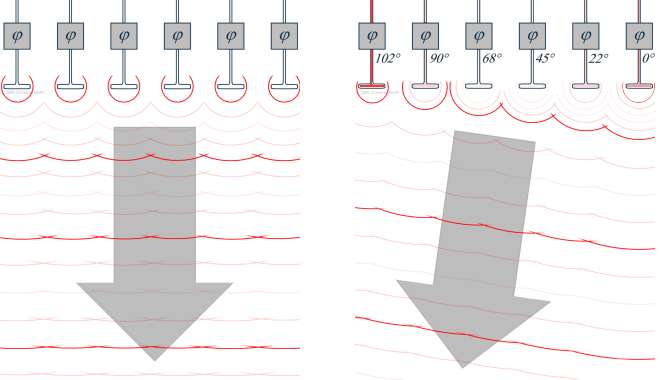
Figure 2: electronic beam-deflection,
left:Boresight, right: Deflected
Figure 2: Animation of the electronic beam-deflection
In the figure 1 (right), the signal is emitted by the upper radiating element with a phase shift of 22 degrees later than of the lower radiating element. Because of this the main direction of the emitted sum-signal is moved slightly upwards.
(Note: Radiating elements have been used without reflector in the figure. Therefore the back lobe of the shown antenna diagrams is just as large as the main lobe.)
The main beam always points in the direction of the increasing phase shift. Well, if the signal to be radiated is delivered through an electronic phase shifter giving a continuous phase shift then the beam direction will be electronically adjustable. However, this cannot be extended unlimitedly. The highest value, which can be achieved for the Field of View (FOV) of a olanar phased array antenna is 120° (60° left and 60° right). With the sine theorem the necessary phase moving can be calculated.
The following figure graphically shows the matrix of radiating elements. Arbitrary antenna constructions can be used as a spotlight in an antenna field. For a phased array antenna is decisive that the single radiating elements are steered for with a regular phase moving and the main direction of the beam therefore is changed. E.g. the antenna of the RRP 117 consists of 1584 radiating elements arranged in an analog beamforming architecture. More sophsticated radar sets use the benefits of a Digital Beamforming architecture.
| Advantages | Disadvantages |
|---|---|
|
|
Possible Arrangements
Linear Arrays
.print.jpg)
Figure 3: linear array of a phased-array antenna
.png)
These antennae consist of lines whose elements are fed about a common phase shifter. A number of vertically about each other mounted linear arrays form a flat antenna.
- Advantage: simple arrangement
- Disadvantage: Ray deflection only in a single plane possible
- Examples given:
- PAR-80 (horizontal beam-deflection) and
- RRP-117 (vertical beam-deflection)
- Large Vertical Aperture (LVA), an antenna with fixed beam pattern.
This kind of the phased-array antenna is commonly used, if the beam-deflection is required in a single plane only because a turn of the complete antenna is anyway carried out ( RRP-117).
.print.jpg)
Figure 4: planar array of a phased-array antenna
.png)
Planar Arrays
These antenna arrays completely consist of singles radiating elements and each of it gets an own phase shifter. The elements are ordered in a matrix array. The planar arrangement of all elements forms the complete phased-array antenna.
- Advantages: Beam steering in two planes or even the digital beamforming is possible.
- Disadvantage: complicated arrangement and more electronically controlled phase shifter needed
- Examples given: AN-FPS-85 and Thomson Master-A
Figure 5: frequency scanning array
Figure 5: frequency scanning array
Frequency Scanning Array
Frequency scanning is a special case of the phased array antenna where the main beam steering occurs by the frequency scanning of the exciter. The beam stearing is a function of the transmitted frequency. This type of antenna is called a frequency scanning array. The normal arrangement is to feed the different radiating elements from one folded waveguide. The frequency scanning array is a special case of serial feeding type of a phased array antenna and is based on a particular property of wave propagation in waveguides. The phase difference between two radiating elements is n·360° at the normal frequency.
By changing the frequency, the angle Θs between the axis of the main beam and the normal on the array antenna changes. Height information is generated using the following philosophy:
- If the transmitted frequency rises then the beam travels up the face of the antenna;
- If the transmitted frequency falls then the beam travels down the face of the antenna.
As frequency is varied, the beam axis will change, and scanning can be accomplished in elevation. The radar set is designed so that it keeps track of the frequencies as they are transmitted and then detects and converts the returned frequencies into 3D display data.
Note that frequency scanning reduces the value of using frequency change as a means of achieving other valuable effects (benefits of pulse compression).
Phase-increment Calculating
The phase shift Δφ between two successive elements is constant and is called phase-increment. How large is this phase shift to reach a certain value of the beam steering?
A linear arrangement by isotropic radiating elements is looked at.
Figure 6: grafic derivation of the formula
| x = d · sin Θs | (1) |
| 360° | = | λ | Δφ = phase shift between two successive elements d = distance between the radiating elements Θs = beam steering |
(2) | |
| Δφ | x |
| Δφ = | 360° · d · sin Θs | (3) |
| λ |
|
Example given: |
|
| Task: |
|
We start with the calculation of the phase-increment.
Because of the trigonometrical function we need a calculator anyway:
Δφ =(360°·15 cm/10 cm)·sin(40°) = 347.1°.
This means the radiating element no. 8 needs the phase shift value
φ8 = 7 · 347.1 = 2429.7°.
On reason of the periodicity of the sine function a phase shifting of n·360° is the same as 0°.
Therefore we can as long as deduct 360° till there is a angle between 0° and 360° of the result.
We get therefore for the phase shifter number 8 (left corner) a phase shift value of
φ8 = 269.7°.
A part of this phase shift is realized by the delay in the feeding line yet.