Digital Beamforming
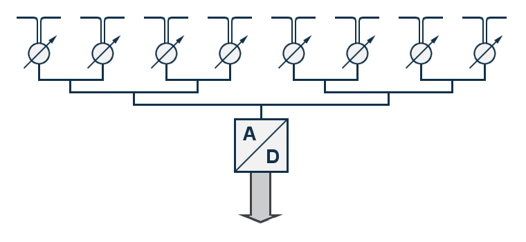
Figure 1: Analogue beam forming of the antenna pattern
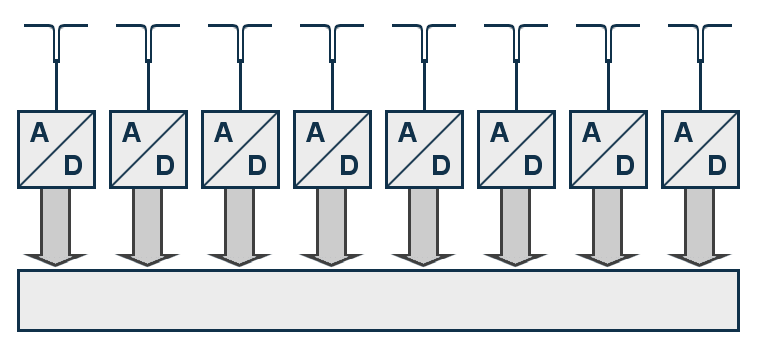
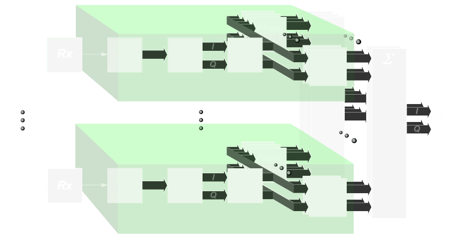
Figure 2: Digital beam forming of the antenna pattern (Courtesy of EADS Defence & Security Ulm)
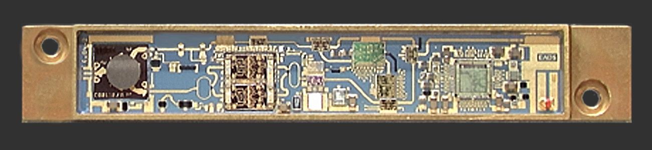
Figure 3: Standardised Modular Transmit-/Receive-Module (SMTRM)
Figure 1: Analogue beam forming of the antenna pattern
Figure 2: Digital beam forming of the antenna pattern
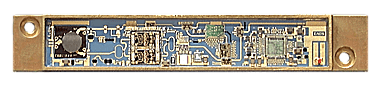
Figure3: Standardised Modular Transmit-/Receive-Module
(SMTRM)
(Courtesy of
Cassidian Ulm,
former
EADS Defence & Security)
Digital Beamforming
Analogue Beam Forming
Analogue Beam Forming (ABF) means, that the received echo signals from each element of the phased array antenna, are combined at the RF carrier frequency level. This analog beam former feeds up to four centralized receiver channels, down-converting the signal to the basic band (or to an intermediate frequency, IF). The following Analogue-to-Digital Converter (ADC) digitizes the IF or the video signals.
Digital Beam Forming
Digital beam forming (DBF) can be realized at element level or at sub array level. In DBF-architecture there are many digital receivers, one own receiver at each of the radiating elements of the antenna. The down-converting to IF-frequency and digitizing the signals is realized at each individual antenna element (or small groups of them). Noise and signal distortion in each receiver are decorrelated among all receivers.
Multiple independent beams steered in all directions can be formed in the digital beam forming processor. The benefits of digital beam forming include:
- improved dynamic range;
- controlling of multiple beams;
- better and faster control of amplitude and phase.
Standardised Modular Transmit-/Receive-Module (SMTR®)
The Transmit-/Receive-Modules are the key components of based on AESA technology digital beam forming. The modules contain a part of transmitters’ power amplifier and parts of the receiver, and can be mass-produced to achieve a better cost/performance ratio. These modules may be used in various programmes with only slight individual adaptations being required. By the compact design the line losses are low during the signal processing. For example, the standardised modular transmit-/receive-modules are used in the X-band multi-function fire control radar of the Medium Extended Air Defence System (MEADS), in the German Armed Forces’ ground surveillance radar BÜR, TerraSAR space radar, and in the Eurofighter’s E-Captor radar.
The SMTRM is a hermetically covered circuit board with the dimensions of 64,5 mm length, a width of 13,5 mm a height of and 4,5 mm. This board contains a power amplifier being in the shape of two monolithically integrated circuits fed with different phaseshift, a ferrite circulator for connection of a transmitter/receiver to the transmit/receive path, a monolithically integrated limiter and a low noise pre-amplifier. The received signal will be down converted into an intermediate frequency. All circuits are performed in Gallium-Arsenide (GaAs) semiconductor technology.
Beam Forming Processor
This ability to organize various antenna patterns at the same time has only become possible with the technology of a digital receiver, because only digital signals can be copied any number of times without loss. In practice, the received signal is converted into an intermediate frequency and then digitized at once. At an IF of 75 MHz, the analog to digital converter requires a sampling frequency of 100 MHz.
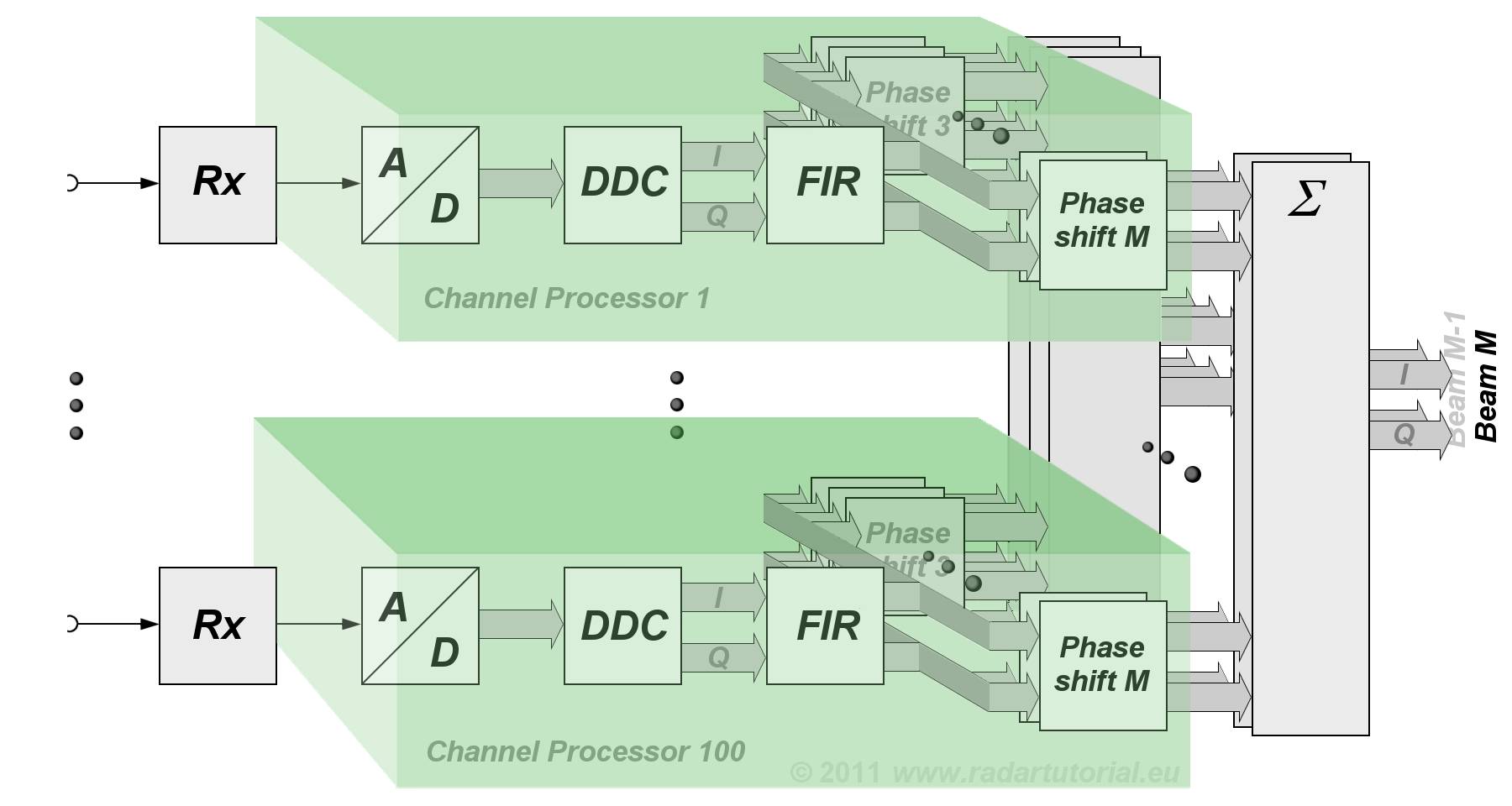
Figure 4: Block diagram of a beam forming processor
The Figure 4 shows a block diagram for a typical beam forming processor. Every single antenna of the phased array antenna has got its own receiver channel and is followed by an own analog-to-digital converter and a digital down converter (DDC). For a correct summation there is a special transversal filter that equalizes the frequency response and corrects the individual propagation delay in this one receiving channel. This transversal filter is also referred to as a finite impulse response filter (FIR). It is tuned in a special automatic calibration routine. For this calibration, a known RF- test signal will be fed into the receiver channel, which is either linearly frequency modulated over the entire bandwidth) or it is a white with a known magnitude. Required weights for suppression of side lobes are also made in this filter. The data of all the analog-to-digital converters of the receive channels are fed as a complex (I&Q) signal via a phase shifter stage in any summation stages. The number of summation stages determines the number of possible simultaneously received antenna beams. In the figure, this number of summation stages is assumed to be 100.