Garbling/Degarbling
Garbling is a fundamental problem in the design of the classical SSR system and the situation is made worse by increased traffic. Aircraft are often closely spaced in range and azimuth but at different heights. Replies from two aircraft will overlap if their range separation is within the equivalent of the 20.3 µs reply length. This is approximately 1.7 Nm. The most serious garbling situations occur when the azimuth separation is very small such that replies from both aircraft are received from all interrogations across the beam. With advanced reply processing techniques and algorithms, it may sometimes be possible to extract all some or all of the replies from the received signal.
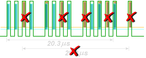
Figure 1: Synchronous garbling: the individual pulses of two different replies cannot be separate and it would decodes an incorrect information
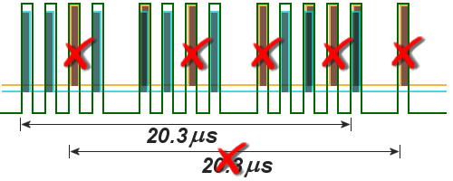
Figure 1: Synchronous garbling: the individual pulses of two different replies cannot be separate and it would decodes an incorrect information

Figure 1: Synchronous garbling: the individual pulses of two different replies cannot be separate and it would decodes an incorrect information
At this, in principle, one distinguishes two manners of the overlapping:
- Non-synchronous Garbling;
- Synchronous Garbling
Two replies overlaps in time such that its time grids are not congruent, so one speaks about Non-synchronous Garbling. Such answers can separated and one by one be decoded correctly!
But if two or more replies overlaps in time such that its time grids are congruent,
so one speaks about Synchronous Garbling.
It cannot to state in the decoding any more, whether this a single impulse belongs to one or the other
ones response telegrams. Through this it would come to the decoding of completely new and wrong replies
and difficult from the original replies. These replies must therefore be disabled!
F1 C2 F2 SPI
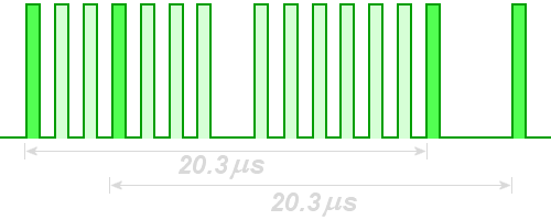
Figure 2: C2-SPI phantom bracket
F1 C2 F2 SPI
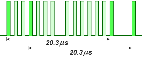
Figure 2: C2-SPI phantom bracket
F1 C2 F2 SPI

Figure 2: C2-SPI phantom bracket
Wirings which reduce the effects of the Garbling are called Degarbling Wirings. Bracket detection is usually implemented by a digital delay line in which the presence of the F1-F2 bracket pair is detected by tapping points 20.3 µs apart with some additional tolerance. Unfortunately the position of the SPI-pulse is spaced 20.3 µs after the C2 pulse and if both pulses are present in a reply then C2-SPI phantom bracket will occur:
But in this case this reply may be decoded and displayed! The airplane with which you have a radio link is of special interest. It would be a pity, if it disappears of the screen as long as the operator talks with the pilot.
Replies which are “Closly Spaced” represent a further special case shown in the bottom one example in the following table.
| Garbling | Pulses | to display |
|---|---|---|
| non-synchronuous Garbling |

|
|
| synchronuous Garbling |

|
|
| C2-SPI phantom bracket |

|
|
| “Closly spaced” | 
|
Table 1: kinds of garbling
Degarble Wiring
To recognize and be able to process the described garbling cases, special degarble wirings are used.
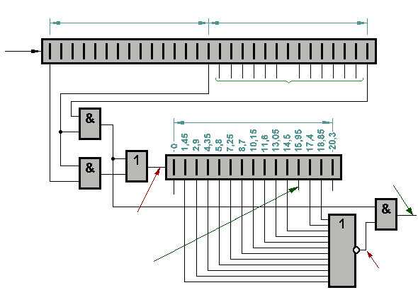
Figure 3: Principle of a degarble wiring
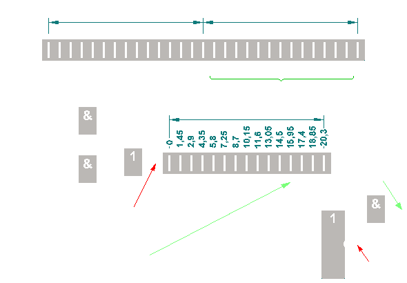
Figure 3: Principle of a degarble wiring
The needed delay lines with the taps of
1,45 µs (pulse grid!)
can be created also as a digital shift register.
The complete process also can be carried out by a processor controlled wiring.
|
Sequences of operation during a correct replay
| ||
|
Sequence of operation during a garbling reconnaissance
| ||
|
Sequences of operation during C2-SPI Phantoms
|
