solid-state Amplifier
power
amplifier
power
amplifier
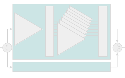
Figure 1: Diagram of solid-state transmitter rack
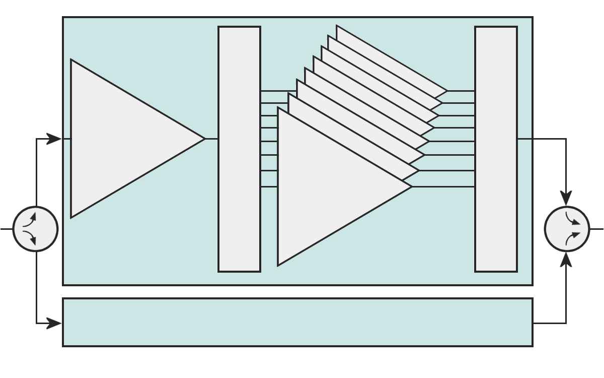
power
amplifier
power
amplifier
Figure 1: Diagram of solid-state transmitter rack

power
amplifier
power
amplifier
Figure 1: Diagram of solid-state transmitter rack
solid-state Amplifier
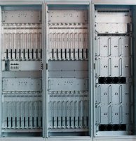
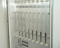
The PSR transmitter of the ASR–E operates in the S-Band and is solid-state. It comprises four clusters, each of which contains eight power modules. All power modules are identical. BITE and status information are displayed on the transmitter front panel, as well as at the operator workstation. The modules can be replaced during transmitter operation (hot replacement) without the disconnection of any cables.
All high power transistors are protected against consequential damage. The availability of the transmitter is nearly 100% because of the graceful degradation capability. The unservicability of one or more power modules will not cause the complete loss of the transmitter and consequently of the ASR-E system. A temporary slight reduction in performance may be accepted. This one power reduction causes a decreasing of the maximum range in a region of typically 1 to 2 percent! Driver and power supply modules are also redundant.
Transmitter Modules
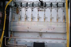
solid-state transmitters are employed in radar sets nowadays however too. At constant phases several MESFET- power amplifiers operates parallelly by means of simple power splitters and adders.
The high performance is assembled by many low-power amplifiers (or amplifier modules). The modules are feed in phase by power splitters. Its respective output powers then are in phase summed up to the complete transmit power. To achieve adequate range with relatively low pulse power, the pulses are intra-pulse modulated often.
Picture gallery of solid-state Amplifiers
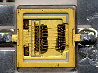
Figure5: GaAs-MeSFET Powermodul in MMIC Technologie, basis for power modules in radar solid-state transmitters

