Double Heterodyning
We must take the following facts into account at the choice of the intermediate frequency:
- No other strong transmitters may work on this frequency.
- This frequency mustn't be very high to be processed more easily.
- This frequency must be adapted to the frequency range of the receiving band to avoid the reception of image frequencies.
The choice of the intermediate frequency can be only a compromise, because once again these demands classically contradict himself.
So far, you have only become familiar with single conversion; however, some receivers use double conversion.

Amplifier
Amplifier
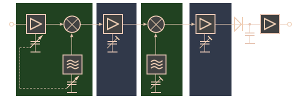
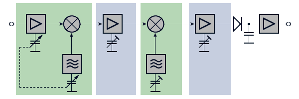
Figure 1: Block diagram of a Double-heterodyne

Amplifier
Amplifier
Figure 1: Block diagram of a Double-heterodyne

Amplifier
Amplifier
Figure 1: Block diagram of a Double-heterodyne (interactive picture)
This method is sometimes referred to as double heterodyning. Receivers using double conversion are very selective and suppress image frequencies to yield sharp signal discrimination. Double conversion receivers also have better adjacent channel selectivity than can be realized in single conversion sets.
Tuner (first converter)
The tuner is a frequency converter, made up of a mixer, the 1st local oscillator (LO), and required filters. The first converter changes the input signal to a usable IF signal that will be e.g. 500 Megahertzes.
The first local oscillator excite a frequency for mixing with the incoming signal to get the intermediate frequency. After the mixer stage the desired intermediate frequency is only reprocessed.
1st IF- Amplifier
The first IF- Amplifier is a relatively narrowband amplifier with a high gain. The first IF has a relatively high value, e.g. 500 Megahertzes. This will cause a high effort of shielding measures.
Automatig gain control measures will be realized here at least.
Second converter
The first IF gets down mixed with a fixed frequency from the 2nd Local Oszillator to the second IF.
Second IF- Amplifier
The second IF- Amplifier is a relatively narrowband amplifier with a very high gain. The frequency is a standard-value between 60 up to 75 Megahertzes. This frequency can be processed uncomplicated. The IF- Amplifier of radar receiver determines the gain, signal-to-noise ratio, and effective bandwidth of the receiver. The typical IF amplifier usually contains from three to ten amplifier stages. The IF amplifier has the capability to vary both the bandpass and the gain of a receiver.
The second IF- Amplifier is often a logarithmic amplifier. A large signal does not saturate the logarithmic amplifier; rather, it merely reduces the amplification of a simultaneously applied small signal. A small echo signal can often be detected by the logarithmic receiver when a normal receiver would be saturated.
Detector
The detector in a microwave receiver serves to convert the IF pulses into video pulses. After amplification, these are applied to the indicator.
Video Amplifier
The video amplifier receives pulses from the detector and amplifies these pulses for application to the indicating device. A video amplifier is fundamentally an RC coupled amplifier that uses high-gain transistors. However, a video amplifier must be capable of a relatively wide frequency response.
