Phase Shifter

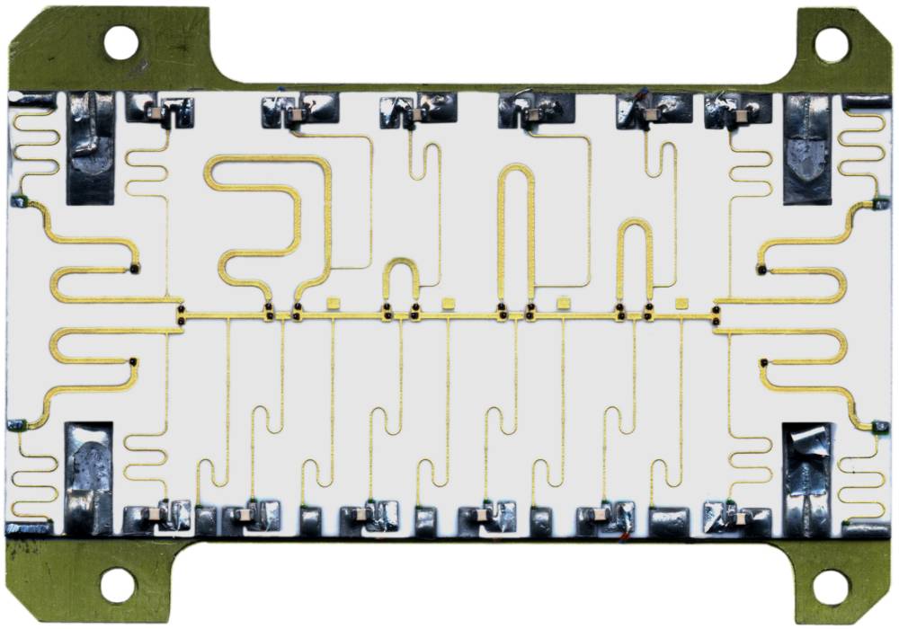
Figure 1: Circuit board with a phase shifter wiring with switched detour lines

Figure 1: Circuit board with a phase shifter wiring with switched detour lines
Phase shifters switching different detour lines are faster than regulators. In the picture a 4 bits-switching phase shifter which is used in radar unit is shown. Different detour lines are switched to the signal way. It is created therefore 16 different phase angles between 0° and 337.5° in steps with a distance of 22.5°.
The inductivities (the thin meander wires as lowpass filters) also can be recognized in the switching voltage supplies for the altogether 24 pin diodes.
Since this phase shifter module works both for the transmitting way and for the reception way, branching between these two paths are attached with pin diode switches on the ceramic strap at the entrance and exit of the module.
The same data word must be used for the reception time and for the transmitting moment.
It is easy to understand: This one radiator, transmitting the latest phase shift,
first receives the echo-signal. Its phase shifter must have the largest detour line for
diagram forming
in a decided direction. The same detour line is needed for a summation of the received
energy and the video-pulse.

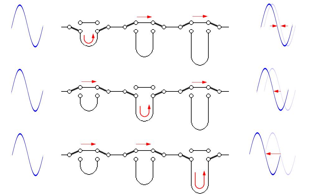
Figure 2: Wiring of the phase shifters delay lines
The phase shifter routes the microwave signal that is supplied to each radiating element through cables of varying length. The cables delay the wave, thereby shifting the relative phase of the output. The illustration shows the three basic delays each phase shifter can introduce. The switches are fast pin diode switches. A central computer calculates the proper phase delay for each of the radiating elements and switches in the appropriate combination of phase-shifters pathways.

