Synthetic Aperture Radar
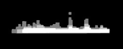
Picture 1: Radar silhouette of a ship, produced with the ISAR-Processor of the Ocean Master
Synthetic Aperture Radar
A Synthetic Aperture Radar (SAR), or SAR, is a coherent mostly airborne or spaceborne sidelooking radar system which utilizes the flight path of the platform to simulate an extremely large antenna or aperture electronically, and that generates high-resolution remote sensing imagery. Over time, individual transmit/receive cycles (PRT's) are completed with the data from each cycle being stored electronically. The signal processing uses magnitude and phase of the received signals over successive pulses from elements of a synthetic aperture. After a given number of cycles, the stored data is recombined (taking into account the Doppler effects inherent in the different transmitter to target geometry in each succeeding cycle) to create a high-resolution image of the terrain being over flown.
How does SAR works?
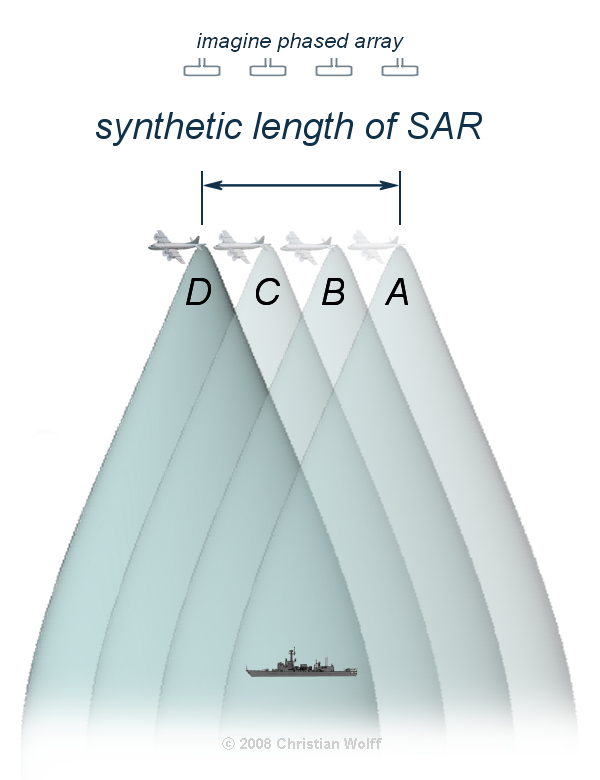
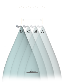
Figure 2: The synthesized expanding beamwidth
The SAR works similar of a phased array, but contrary of a large number of the parallel antenna elements of a phased array, SAR uses one antenna in time-multiplex. The different geometric positions of the antenna elements are result of the moving platform now.
The SAR-processor stores all the radar returned signals, as amplitudes and phases, for the time period T from position A to D. Now it is possible to reconstruct the signal which would have been obtained by an antenna of length v · T, where v is the platform speed. As the line of sight direction changes along the radar platform trajectory, a synthetic aperture is produced by signal processing that has the effect of lengthening the antenna. Making T large makes the „synthetic aperture” large and hence a higher resolution can be achieved.
As a target (like a ship) first enters the radar beam, the backscattered echoes from each transmitted pulse begin to be recorded. As the platform continues to move forward, all echoes from the target for each pulse are recorded during the entire time that the target is within the beam. The point at which the target leaves the view of the radar beam some time later, determines the length of the simulated or synthesized antenna. The synthesized expanding beamwidth, combined with the increased time a target is within the beam as ground range increases, balance each other, such that the resolution remains constant across the entire swath.
The achievable azimuth resolution of a SAR is approximately equal to one-half the length of the actual (real) antenna and does not depend on platform altitude (distance).
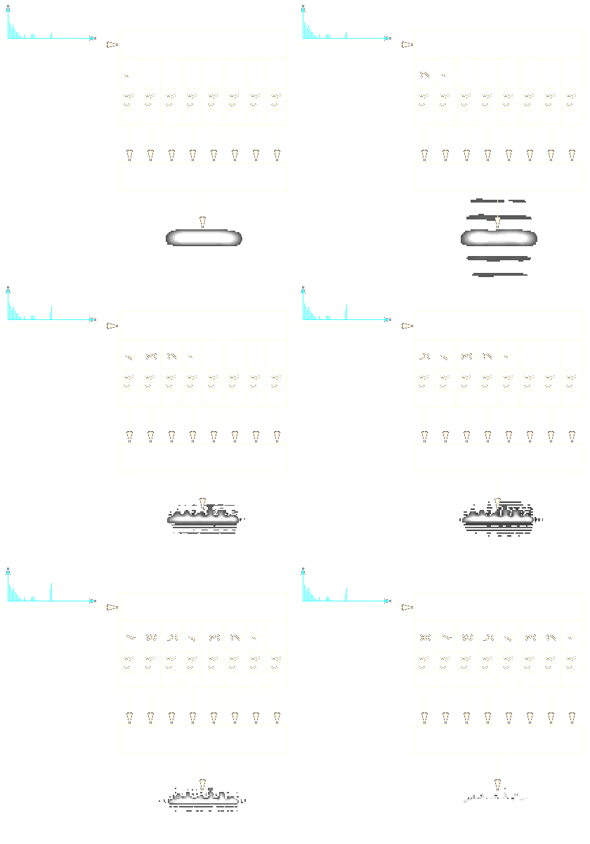
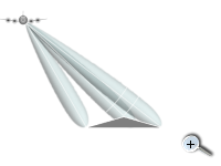
Figure 3: Principle of SAR- operation
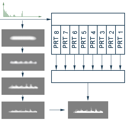
Figure 3: Principle of SAR- operation

Figure 3: Principle of SAR- operation
The requirements are:
- stable, full-coherent transmitter
- an efficient and powerful SAR-processor, and
- exactly knowledge of the flight path and the velocity of the platform.
Using such a technique, radar designers are able to achieve resolutions which would require real aperture antennas so large as to be impractical with arrays ranging in size up to 10 m.
A Synthetic Aperture Radar was used on board of a Space Shuttle during the Shuttle Radar Topography Mission (SRTM).
SAR radar is partnered by what is termed Inverse SAR (abbreviated to ISAR) technology which in the broadest terms, utilizes the movement of the target rather than the emitter to create the synthetic aperture. ISAR radars have a significant role aboard maritime patrol aircraft to provide them with radar image of sufficient quality to allow it to be used for target recognition purposes.
Slant-range distortion
The slant-range distortion occurs because the radar is measuring the distance to features in slant-range rather than the true horizontal distance along the ground. This results in a varying image scale, moving from near to far range.
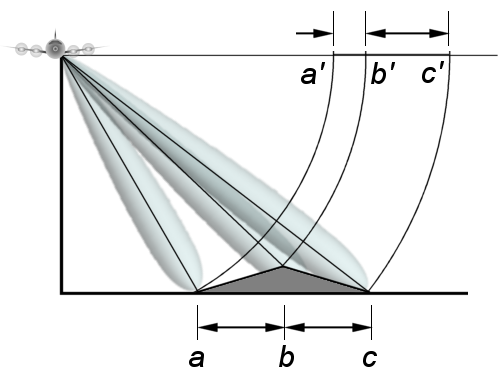
Figure 4: Foreshortening
- Foreshortening occurs when the radar beam reaches the base of a tall feature tilted towards the radar (e.g. a mountain) before it reaches the top. Because the radar measures distance in slant-range, the slope (from point a to point b) will appear compressed and the length of the slope will be represented incorrectly (a' to b') at the image plane.
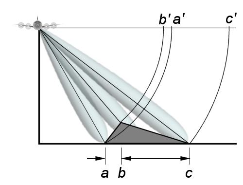
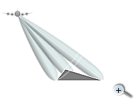
Figure 5: Layover
- Layover occurs when the radar beam reaches the top of a tall feature (b) before it reaches the base (a). The return signal from the top of the feature will be received before the signal from the bottom. As a result, the top of the feature is displaced towards the radar from its true position on the ground, and „lays over” the base of the feature (b' to a').
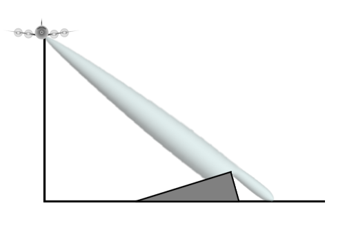
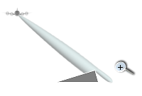
Figure 6: Shadowing
- The shadowing effect increases with greater incident angle θ, just as our shadows lengthen as the sun sets.

