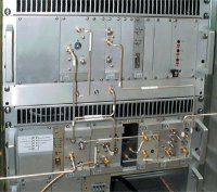
Exciter
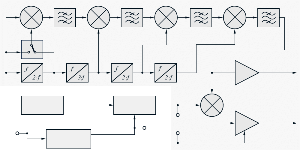
A radar exciter provide coherent frequency and timing relationships performed by (an older) analog synthesizer or (a newer) direct digital synthesis (DDS), capable of creating high-resolution wideband waveforms for radar systems. The exciter provides fully coherent receiver local oscillator signals at radar frequency band as well as requisite, auxiliary high frequency clock signals. The exciter function is divided into an internal frequency synthesizer and an upconverter.

Oszillator
Generator
control
(pulsed)
Figure 1: Diagram of an analog radar exciter and the up-converting of frequencies for use in transmitter and receiver.
TP1: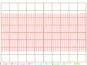
TP2: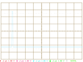
TP3: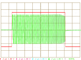
TP4: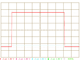
Oscillator
Generator
control
(pulsed)
Figure 1: Diagram of an analog radar exciter and the up-converting of frequencies for use in transmitter and receiver.

(pulsed)
Figure 1: Diagram of an analog radar exciter and the up-converting of frequencies for use in transmitter and receiver.
(If this page shall be printed, then please print in a landscape format!)
The low phase noise frequency synthesizer provides the different basic frequencies to achieve frequency agile capabilities. In Figure the frequency synthesizer is adumbrated as a simple switch between 60 and 120 MHz. In reality this is a very complex subblock. Recent radar systems use even phase lock loop (PLL) architecture.
The upconverter produces the system’s transmit carriers and the local oscillator frequencies for receivers downconverter and detectors, to convert the received RF-backscatter into wideband first IF and narrowband second IF. System functions included in both synthesizer and upconverter include; switches, limiters, variable attenuators and filtering to reduce spurious signals.
Output signal spectral performance is achieved by use of quartz crystals in the master oscillator and frequency synthesis techniques as cascaded stages of narrowband resonator filters, regenerative frequency division, and low noise, diode doublers and step recovery diode frequency multiplication.
The sub-assemblies frequency synthesizer, upward mixer, waveform generator and master oscillator are integrated under the denomination Exciter or Signal Generator in some radar sets. This radar assembly is combined with the receiver in a single rack often, as shown in figure 2.

