Radar Waveform
Radar Waveform
The inner structure of the transmitted signal is usually called the Radar Waveform. The general term includes both the very simple pulse modulation (so-called “Keyed ON/OFF”- Modulation) and non-linearly internally modulated transmit pulses that are generated in a complicated manner. These signals may have a complex structure for a pulse compression radar.
In general, all modulations used in continuous wave (CW) radar can also be used within the short or long pulse of a pulse radar.
Waveform-Generator
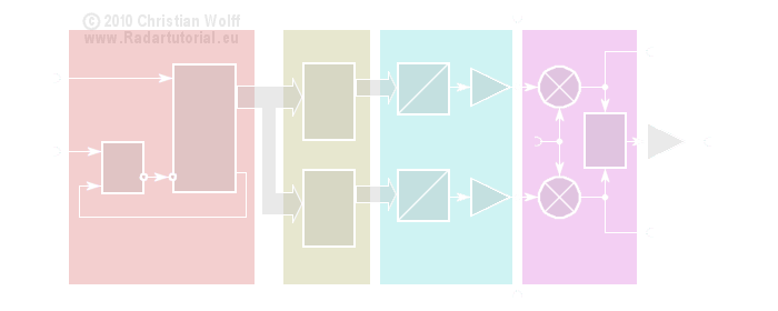
A waveform generator generates the transmitting signal on an IF- frequency. It permits generating predefined waveforms by driving the amplitudes and phase shifts of carried microwave signals. SAW devices, which were the mainstay of pulse compression in the 1980s, were also the prime mechanism for waveform generation when used as expanders. Since these waveform signals are used as a reference for the receiver channels too, there are high requirements for the time and frequency stability.
Counter
PROM
PROM
)
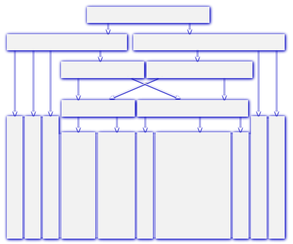
Figure 1: an e.g. Block diagram of a digital waveform generator (DWG) for a non-linear compressed pulse
Counter
PROM
PROM
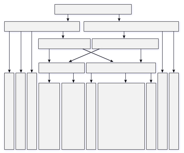
Figure 1: an e.g. Block diagram of a digital waveform generator (DWG) for a non-linear compressed pulse
Counter
PROM
PROM
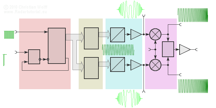
Figure 1: an e.g. Block diagram of a digital waveform generator (DWG) for a non-linear compressed pulse 1) (interactive picture)
Digital Waveform Generation
Digital Waveform Generation (DWG) is a memory-based Arbitrary Waveform Generator (AWG). The desired waveform may be described by a mathematical function, and each discrete value of the function is stored as a digital word in a memory. The memory will be counted using the system clock and provides the values continuously at the output. There, they are converted to an analog voltage. The individual values of time in quick succession give the synthesized waveform.
The finally waveform is constructed of e.g. 2048 discrete voltage steps here. Its values of amplitude and phase are stored in programmable memories (PROMs). A change of the waveform is only possible by replacing the PROMs by the manufacturer.
In the by the Radartutorial self-developed Didactical Multifunction Radar are used instead of two PROM fast static RAM with a capacity of 64 Kbytes each with 16 bits. Provided by a laptop via USB, an ATMEL processor can load these memories with the needed values. Thus, it is possible to generate any waveform, ranging from ultra-short pulses for classical pulse radar, via intrapulse modulation (with subsequent pulse compression) to all forms of modulation of frequency modulated continuous wave radar (FMCW radar).
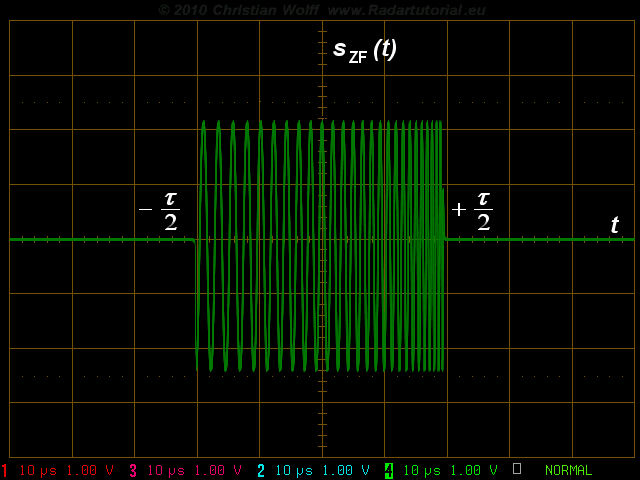
The processing of an I & Q- phase- detector is arranged reverse virtually. This method of design the transmitting pulses gives the advantage, that the waveform is digitally described for a computer-controlled signal processing. A digital processor can execute the pulse compression now.
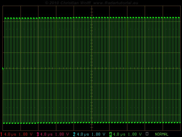
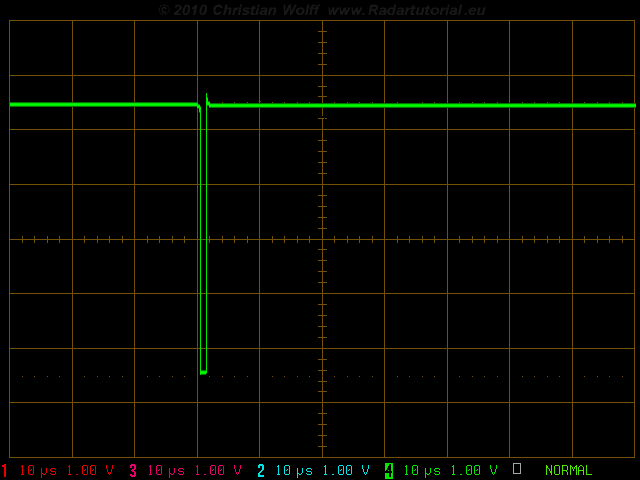
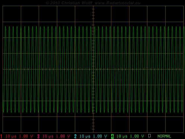
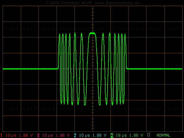
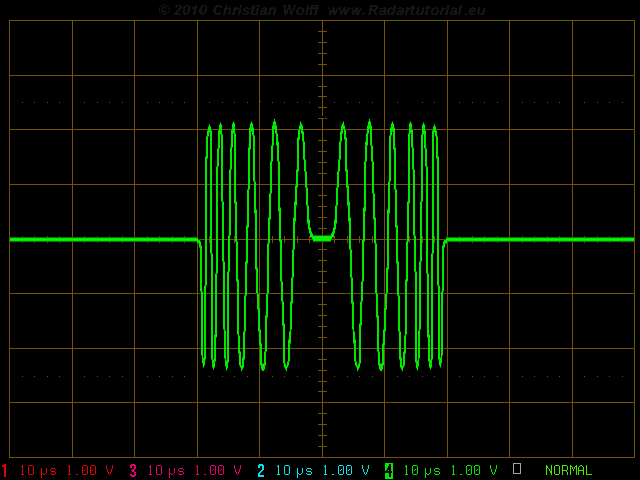
1) A very (unusual) low intermediate frequency of 470 kilohertzes was choosen here to visualize the high-frequencies in the schreen-shoots of the oscilloscope.