Surface Acoustic Wave Device
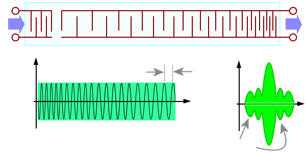
Figure 1: SAW- device width linear decreased spacing of the transducers
Figure 1: SAW- device width linear decreased spacing of the transducers
Surface Acoustic Wave Device
SAW devices (Surface Acoustic Wave) are extensively deployed in currently using the pulse compression operational systems. They are built on a piezoelectric substrate, which propagates acoustic waves along the surface.
The low speed of the waves means that significant delays can be implemented in a small space. The inter digital transducers convert the electrical signal to acoustic waves and are made of metallic thin films deposited on the substrate. It is clearly easy to fabricate the required shapes by photographic etching techniques. The frequency response of the delay line depends on the spacing of these transducers.
In the example shown, the received pulse is input at the left hand and the compressed output pulse results at the right hand end. The highest frequency suffers the largest delay and overlays the lowest frequency. All frequency parts of the input signal are slid into the same Rangecell.
The presence of harmonics in the signal input will hamper the output waveform of each filter. The output of the compression filter consists of the compressed pulse accompanied by responses at other times (i.e., at other ranges), called time or range sidelobes.