Timing and Control: The Radar Trigger
The components in radar must operate together and in proper time, so every radar needs a number of control pulses or triggers. They determine when and which assembly begins in each pulse period with its work. In ancient radars, a trigger generator produced needle pulses with the help of a vacuum tube wired to as asynchronous blocking generator. Modern radars with higher performance operate coherently. The trigger pulses are very short rectangular pulses for edge-controlled or controlled by the pulse duration inputs. They are produced from a highly stable master oscillator by frequency counting and following logical combinations here. The names and numbers of triggers vary from radar to radar.
counter
generator
generator
Generator
Generator
Converter
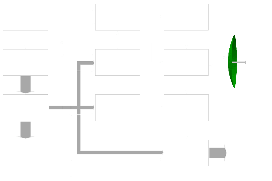
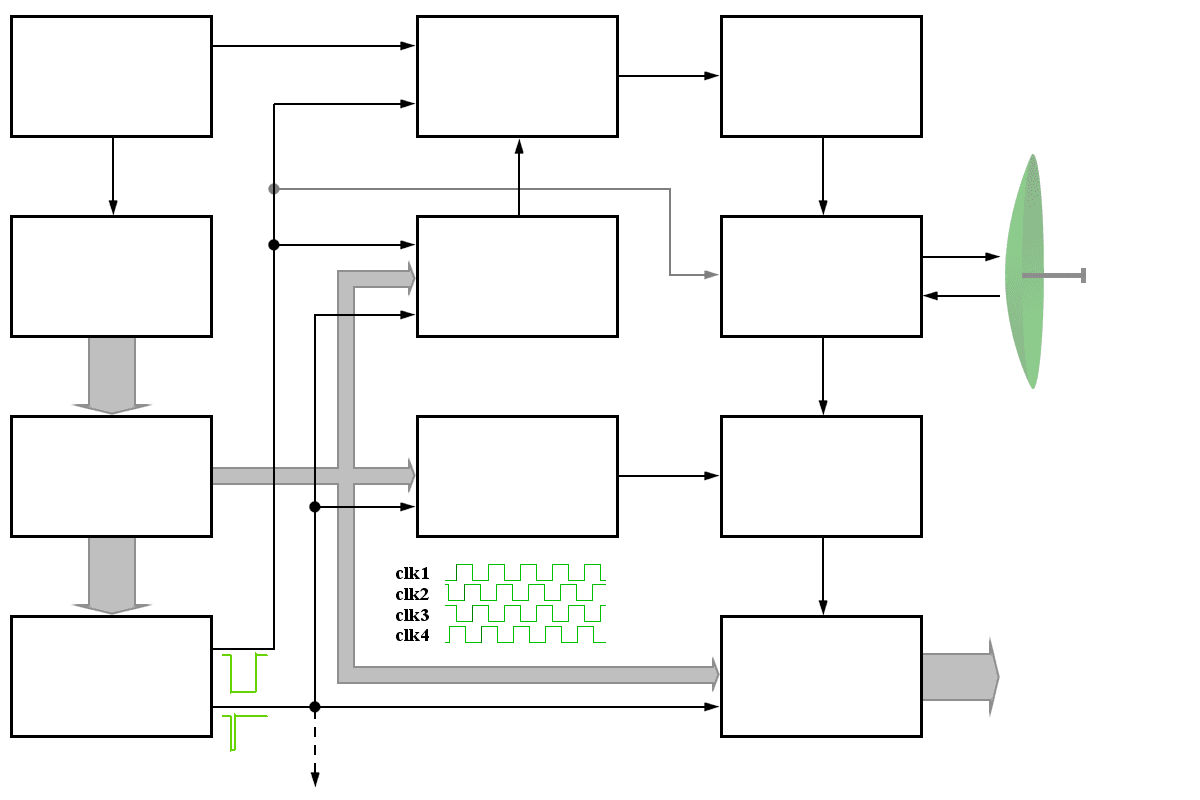
Figure 1: Timing, trigger generation, and distribution.
counter
generator
generator
Generator
Generator
Converter
Figure 1: Timing, trigger generation, and distribution.
counter
generator
generator
Converter
Figure 1: Timing, trigger generation, and distribution.
Figure 1 shows a commonly used trigger generation in a coherent manner. A central master oscillator, often 100 MHz, provides a reference phase for the transmitted and received signals. This master oscillator can be even synchronized with a UTC-time source distributed by GPS-Satellites. Mostly this is a Quartz-oscillator only. This one can be mounted in a rheostat for higher requirements for frequency accuracy and reduced phase jitter.
The oscillator frequency is divided down to provide clocks to delay and synchronize all the triggers, the digital signal processors, and computers. First, all divided frequencies are distributed to the clock generator and the trigger generator.
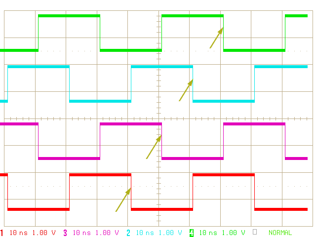
Figure 2: four staggered clocks
The clock generator produces a system clock for the whole radar system. The relatively high frequency of the master oscillator provides a good accuracy but this high frequency cannot be distributed to all subassemblies. For this frequency, all wirings have got characteristics like an antenna. For 100 MHz a line with the length of about 1 meter is a resonant dipole yet. So a frequency of e.g. 25 MHz is used as a system clock. To provide the same accuracy as a 100 MHz clock, there are four lines with each the 25 MHz clock, but every clock of Clock 1 to Clock 4 is delayed with 1/100 MHz = 10 ns. These four clocks are distributed and every subassembly can use one of these clocks depending on internal run time and delays in the wirings.
The most important triggers are the so-called Zero Range Trigger – equal with the start of the transmitted pulse mostly; and second the pulse with the length of the waveform. Both pulses can be fitted with offsets: some assemblies need a pre-trigger some microseconds before the start of the waveform trigger. These pre-triggers control radar assemblies that are not active on the transmitting time, e.g. the receiver, the radar signal processing, and the displays. The pulse containing the length of the transmitters waveform controls radar assemblies that are active during the transmitting time, e.g. the waveform generator, the exciter, and the (using PIN-diodes) duplexer. This pulse can be fitted width offsets too but here the offset ist symmetric: e.g. the transmitters power amplifier must get it's power feed before the waveform begins and must hold a tad longer than the waveform.