P- 12 NP “Spoon Rest B”
Description of the radar set, tactical-technical characteristics

| Specifications | |
|---|---|
| frequency: | 150 - 170 MHz
(lower VHF-Band) |
| pulse repetition time (PRT): | 2.77 milliseconds |
| pulse repetition frequency (PRF): | 360 Hz ±10% |
| pulsewidth (τ): | 6 µs |
| receive time: | 2.4 milliseconds |
| dead time: | 377 µs |
| peak power: | 160 to 250 kW |
| average power: | up to 540 watts |
| instrumented range: | 200 NM |
| range resolution: | ½ NM |
| accuracy: | |
| beamwidth: | 8° |
| hits per scan: | > 15 |
| antenna rotation: | 6 … 30 seconds (0 … 10 rpm.) |
| MTBCF: | |
| MTTR: | |
P- 12 NP “Spoon Rest B”
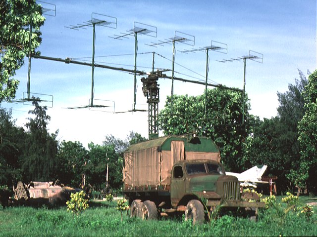
The former Soviet Union had considerable successes in the development of VHF- radar units.
The assortment of VHF- radar units in the army and the air force sufficed of the P 8 over the P 12 up to the P 18 radar sets.
One of them is the mobile variant NP, a version of the P 12 installed into two caravans.
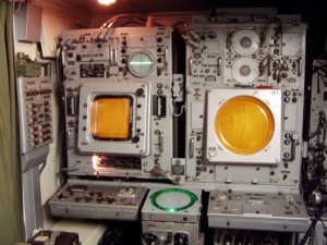
The radar unit also has an E-scope next to the plan position indicator (PPI). The
elevation angle measures the goniometer (the green luminescent scale between the
maintenance paneels) by a phase comparison between the two echo signals received by the both antenna planes.
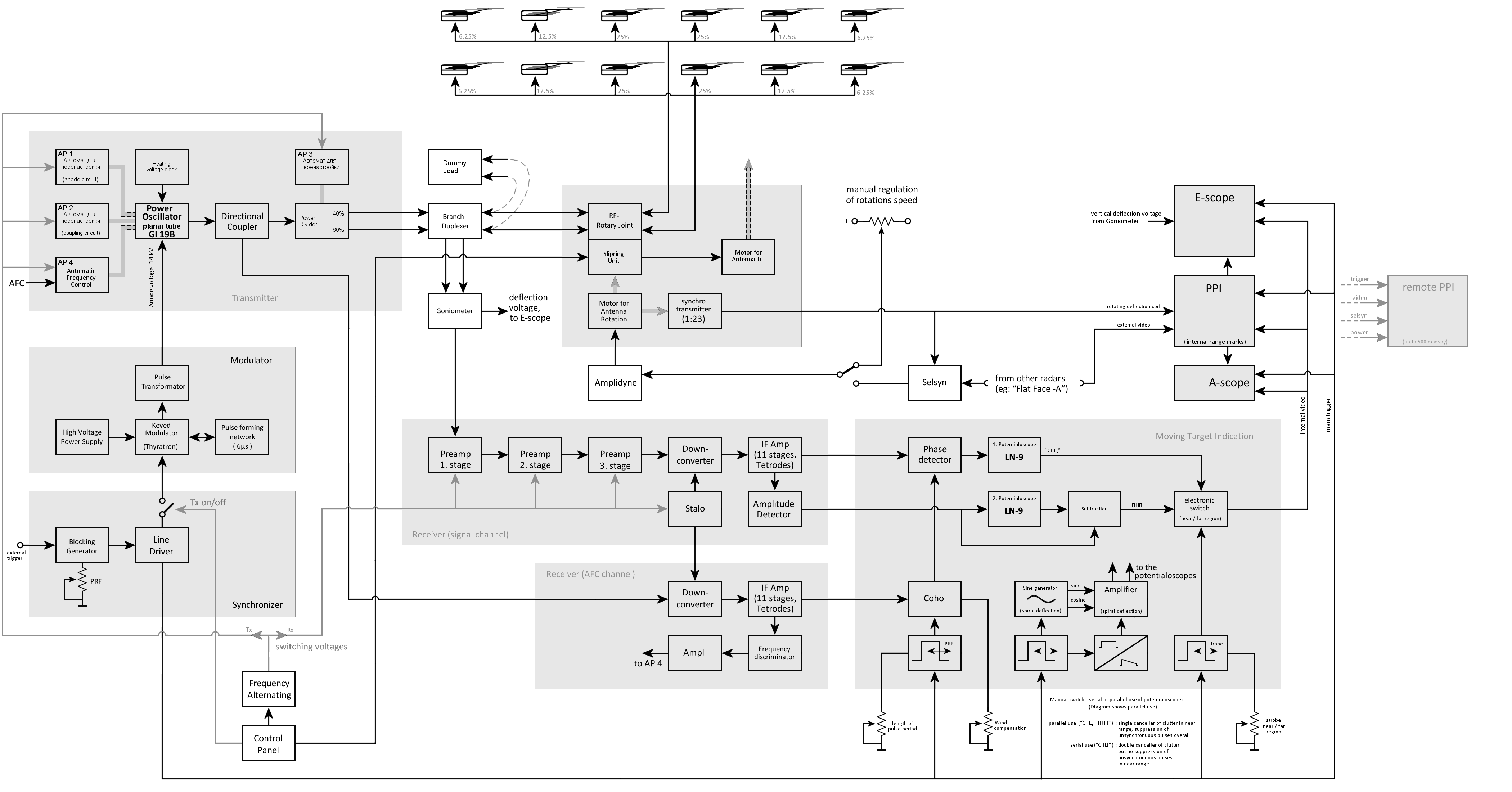
The Goniometer produced a standing wave of the received RF impulses on two slip rings fed by the two antenna groups. An electrical engine alternately moves a measuring contact on the slip rings and simultaneous a variable resistor delivers the vertical deflecting voltage to the RHI-scope. The voltage difference of the slip rings reaches the value zero in a certain position. The mechanical angle of this position corresponds to the elevation angle of the target. With a nomogram on the screen the shown elevation angle could be converted to a height. But the method reduces, however, the maximum range of the radar unit. Therefore the crew usually switched off the Goniometer.
The radar unit P 12 can be synchronized with other radar units and then the PPI-scope shows both received echos. If two stations working by the same frequency are in a favorable distance to each other, her maximum obtainable range can be increased by interference.
The trailer-mounted P-12 NP (1RL 14 PIR) “Spoon Rest B” is a derivate of the truck-mounted P-12 MA “Spoon Rest A”. The later version P-12 NA is a truck-mounted version again.
