Block Diagram of an A-Scope
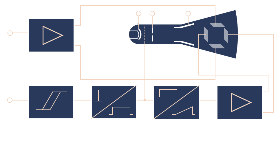
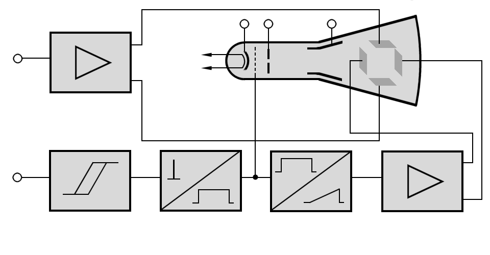
A functional block diagram of a simple A-Scope is represented in the following interactive graphic:

f
(video) amplifier
ray tube
gate
generator
generator
deflection
amplifier
Figure 1: Block diagram of an A-scope

f
(video) amplifier
ray tube
gate
generator
generator
deflection
amplifier
Figure 1: Block diagram of an A-scope

f
(video) amplifier
ray tube
gate
generator
generator
deflection
amplifier
Figure 1: Block diagram of an A-scope (interactive picture)
Block Diagram of an A-Scope
Figure 1 shows a simple Block Diagram of an A-Scope. The modules of A-scope have the following function:
Video Amplifier
The video amplifier increases the amplitude of the input signal level required
for the deflection of the CRT beam. The deflection amplifier must not have any other effect on the signal,
such as changing the shape (called distortion).
If negative echo signals are not expected, then a d.c. voltage is overlayed
to move the trace to the bottom line of the screen.
Cathode-ray tube (CRT)

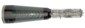
Figure 2: Russian Cathode Ray Tube 8LO4i

Figure 2: Russian Cathode Ray Tube 8LO4i
A cathode-ray tube consists of an electron gun, a deflection system, and a fluorescent screen. All of the elements of a CRT are enclosed in the evacuated space inside the glass CRT.
- The electron beam is developed, focused, and accelerated by the electron gun. It consists of a heater and a cathode. The cathode is indirectly heated and emits a cloud of electrons.
- They are focused into a narrow beam by grid cap (the so-called “Wehnelt cylinder”) This grid is a hollow metal tube placed over the cathode. A small opening is located in the center of a baffle at the end opposite the cathode. The control grid is maintained at a negative potential with respect to the cathode to keep the electrons bunched together.
- A high positive potential on the anodes pulls electrons through the hole in the grid. Because the grid is near the cathode, it can control the number of electrons that are emitted. The high positive potential of the anode attracts the electrons toward the screen.
- The deflection system consists two sets of deflection plates placed at right angles to each other inside the CRT. The electric field between these plates moves the beam horizontally and vertically across the screen. The vertical-plate potential difference follows the voltage of the echosignal. The horizontal-plate potential follows the passage of time.
- The fluorescent screen is coated with a phosphorous material that glows when struck by the electrons.
Trigger control
A synchronizing pulse is required to trigger the sweep of the a-scope. These pulses ensure that the sweep on the a-scope starts from its point of origin each time the radar transmits. The leading edge of the transmitted pulses must be seen at the left side of the screen. This is the begin of delay time (and the range) measurement.
The trigger pulse must be additionally delayed often. The triggercontrol then provides timing for the intensity gate generator and the sawtooth generator.
Intensity Gate Generator
The intensity gate generator provides a gate which unblanks the crt during sweep periods. The duration of its rectangle pulse determines the trace time of the sweep. During the retrace time (flyback) the sweep must be blanked. In this time the sweep moves to its origin at the left side of the screen.
Sawtooth Generator

Figure 3: Sawtooth waveform

Figure 3: Sawtooth waveform
A negative amplitude of the deflection voltage moves the beam left of the screen, a positive voltage moves the beam right of the screen. The waveform amplitude of a sawtooth causes a uniform movement of the beam across the screen (called trace). The leading edge of the sawtooth has to be exactly linear. The rise time of the sawtooth determines the choosen scale of ranging. The trailing edge of the waveform (retrace time), quickly deflects the beam back to the starting point.
Horizontal Deflection Amplifier
The horizontal deflection amplifier (time base amplifier) increases the amplitude of the sawtooth waveform level required for the deflection of the CRT beam.
In addition to the parts shown here for, the A Scope also contains assemblies for power supply. Sometimes it contains assemblies to the production of various range marks or grids, too.
