Block diagramm of a PPI-scope
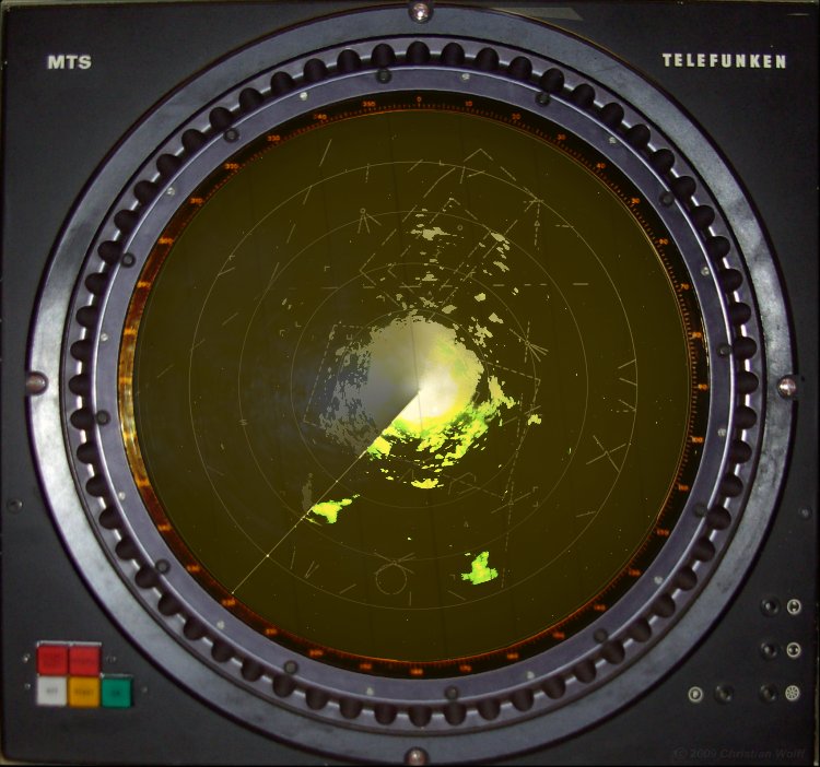
Figure 1: View of a PPI-scope
The PPI-scope uses a radial sweep pivoting about the center of the presentation. This results in a map-like picture of the area covered by the radar beam. A long-persistence screen is used so that the display remains visible until the sweep passes again.
Bearing to the target is indicated by the target's angular position in relation to an imaginary line extending vertically from the sweep origin to the top of the scope. The top of the scope is either true north (when the indicator is operated in the true bearing mode) or ship's heading (when the indicator is operated in the relative bearing mode).
synchronizer
Information
coil
coils
circuit
control
supply
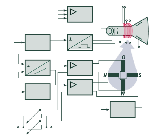
Figure 2: Block diagramm of a PPI-scope
synchronizer
Information
coil
coils
circuit
control
supply
Figure 2: Block diagramm of a PPI-scope
synchronizer
Information
coils
circuit
control
supply
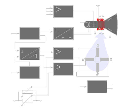
Figure 2: Block diagramm of a PPI-scope (interactive picture)
Gate Circuit
The gate circuit develops pulses which synchronize the indicator with the transmitter. The gate circuit itself is synchronized by trigger pulses from the synchronizer. It then provides timing for the intensity gate generator, sweep generator circuit, and the sweep control circuit.
While the PPI-Scope at older radar sets is synchronized by trigger pulses directly from the modulator, e.g. the Synchronizer of the ASR-910 provides a special scope-trigger (TA-39).
Intensity Gate Generator
The intensity gate generator provides a gate which unblanks the crt during sweep periods. The intensity of the trace appearing on the crt is determined by the dc level of this gate. This circuit is also synchronized by the gate circuit.
Video Amplifier
The video amplifier circuit amplifies the video signal from the receiver and applies it to the crt intensity-modulating element (control grid). At this a balanced relationship is necessary between brightness and contrast.
The brightness of the grid of the azimuth- and range marks should be adjusted very weakly.
Sweep Control Circuit
To synchronize sweep rotation with antenna rotation, you must convert antenna azimuth (bearing) information into electrical signals. These signals, usually provided by synchros, control the amplitudes and polarities of the sawtooth sweep currents applied to the deflection coils.
The amplitudes of the sawtooth sweep currents are varied sinusoidal (like a sine wave), corresponding to the rotation of the antenna.
Figure 3: Gauge of the range with the sawtooth- voltage
Sawtooth- Generator
The sweep generator circuit produces currents which deflect an electron beam across the crt. Varying voltages from the sweep control circuit are applied to deflection coils. Gate voltages determine sweep rate, and therefore, the effective distance (range) covered by each sweep.
Figure 4: sweep rotation with fixed coils
The amplitudes of the sawtooth sweep currents are varied sinusoidal (like a sine wave), corresponding to the rotation of the antenna. Notice that there is a 90 degree phase difference between the amplitude variations of the horizontal and vertical waveforms.
The sawtooth current is required to produce a linear trace. A deflection coil may be considered equivalent to the circuit shown in the diagram. Because of the inductance of the coil, a trapezoidal voltage must be applied across the coil to produce a sawtooth of current through it.
Cathode Ray Tube (CRT)
All CRT's have three main elements: an electron gun, a deflection system, and a screen. The electron gun provides an electron beam, which is a highly concentrated stream of electrons. The deflection system positions the electron beam on the screen, and the screen displays a small spot of light at the point where the electron beam strikes it.
There are two possibilities for the deflection of the electron beam:
- the electrostatic controlled deflection and focusing, and
- the electromagnetic controlled deflection and focusing of the electron beam.
The primary difference between electromagnetic and electrostatic cathode-ray tubes lies in the method of controlling deflection and focusing of the electron beam. Both types employ electron guns and use electrostatic fields to accelerate and control the flow of electrons. The physical construction of a crt employing electromagnetic deflection is similar to an electrostatic type.
A PPI requires a crt in which the screen is coated with a long-persistence phosphor. This is necessary because each target reflects energy for only a short period of time during each rotation of the antenna. Therefore, the target indication on the face of the crt must be able to continue to glow during the portion of antenna rotation when the target is not reflecting energy.
These screen systems have a dynamics of 12 dB maximum. Therefore the signal-noise-ratio of the echo signals has the optimal value of 4 to 1.
Deflection Current Amplifier
Electron deflection in the electromagnetic crt is proportional to the strength of the magnetic fields. Magnetic field strength depends on current in the coils. The sweep circuits associated with electromagnetically deflected cathode-ray tubes must provide currents, rather than voltage, to produce the desired beam deflection.
Figure 5: trapezoidal sawtooth
A sawtooth current is required to produce a linear trace. Because of the inductance of the coil, a trapezoidal voltage must be applied across the coil to produce a sawtooth of current through it. This is illustrated in beside view:
Deflection Coils
Azimuth indication of the PPI requires that the range trace rotate about the center of the screen. A very simple means of achieving sweep rotation is to cause the deflection coil to rotate about the neck of the crt in synchronization with the antenna motion (e.g. the PPI-scope of the old Russian radar P–12). This method, however, has the disadvantages of inaccuracy and maintenance complications inherent to any mechanical gear-train assembly.
More modern PPI systems employ fixed deflection coils like shown in the functional diagram, and use special circuits to electronically rotate the magnetic field. (E.g. PPI-scope of the radar set ASR-910.) Two coils in series are positioned in a manner that causes the magnetic field produced to be in a vertical plane. The other two coils, also connected in series, are positioned so that their magnetic field is in a horizontal plane. The coils (N-S) which produce a horizontal field are called vertical deflection coils and the coils (E-W) which produce a vertical field are called horizontal deflection coils. This may be more clearly understood if you recall that an electron beam will be deflected at right angles to a deflecting field.
Power Supply
The power supply produces all voltages needed to operate the indicator. It also includes protective devices and metering circuits.
(Although not shown in the basic block diagram, many indicators contain circuits which
aid in range and bearing determination. These circuits are also synchronized by the gate
circuit.)