Synchros
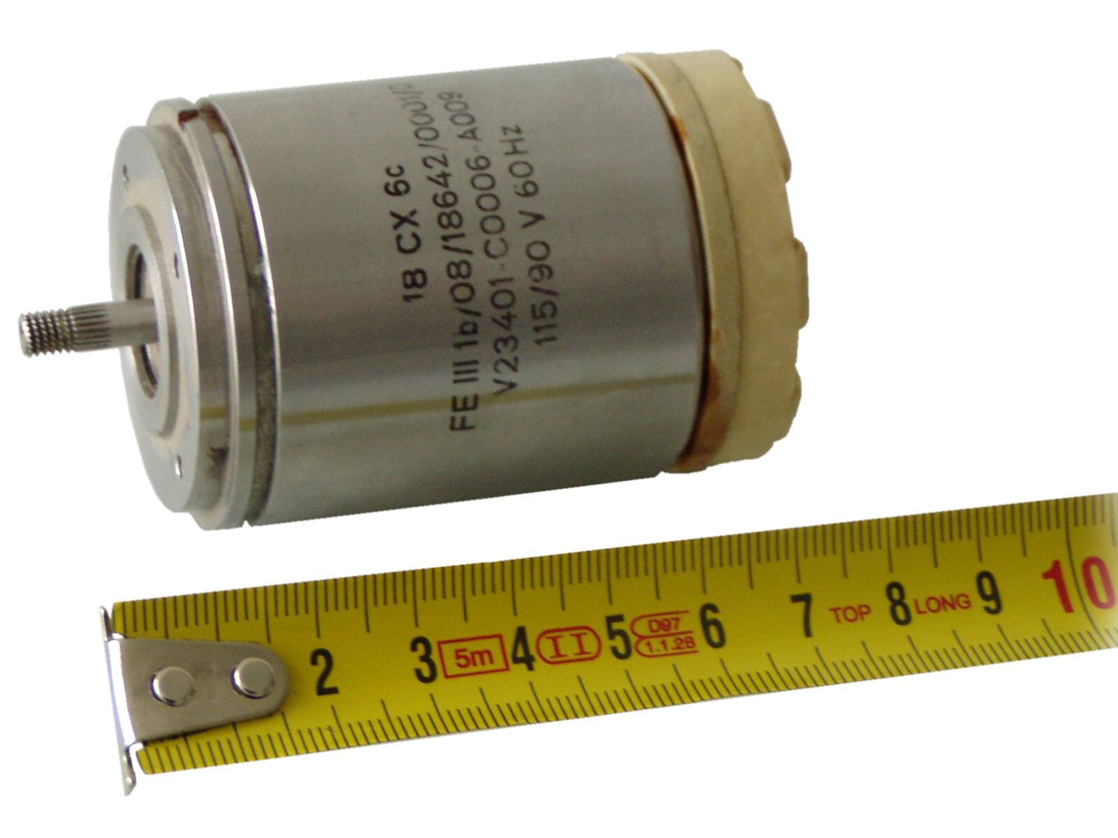
Figure 1: A synchro looks like a very small three-phase current electric motor (diameter: 1½").
Synchros
The term “synchro” is an abbreviation of the word “synchronous”. It is the name given to a variety of rotary, electromechanical, position-sensing devices.
A synchro resembles a small electrical motor in size and appearance and operates like a variable transformer.
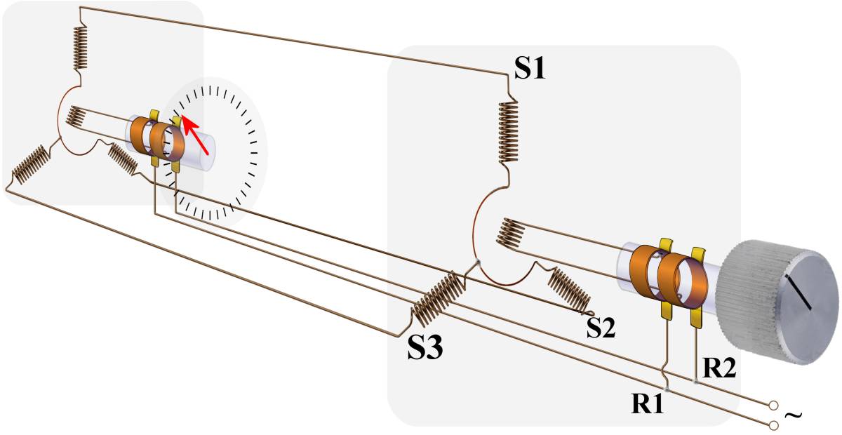
Figure 2: Principle of torque synchro measurement.
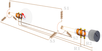
Synchros are simply variable transformers. Each synchro contains a rotor, similar in appearance to the armature in a motor, and a stator, which corresponds to the field in a motor. Torque-synchro systems are classified „torque” because they are mainly concerned with the torque or turning force required to move light loads such as dials, pointers, or similar indicators. The positioning of these devices requires a relatively low amount of torque. The synchro stator is composed of three Y- or Δ-connected windings spaced 120 degrees apart. Both stationary and rotating coils are connected to the same supply voltage (most 400 Hz or 50 Hz AC with U = 110 V).
The torque developed in a synchro receiver results from the tendency of two electromagnets to align themselves. Since the rotor can be turned and the stator usually cannot, the stator must exert a force (torque) tending to pull the rotor into a position where the primary and secondary magnetic fields are in line. The strength of the magnetic field produced by the stator determines the torque. The field strength depends on the current through the stator coils. As the current through the stator is increased, the field strength increases and more torque is developed.
Control synchros are used in systems that are designed to move heavy loads such as gun directors, radar antennas, and missile launchers. A positioning servo system using a control synchro system consisting of a servomotor, a servo amplifier, a control transmitter (load) and a control transformer.
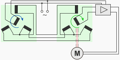
Figure 3: Typical electromechanical follow-up servo system.
The error signal is amplified by the servo amplifier and applied to the servomotor. The servomotor turns the load, and through a mechanical linkage called „response”, also turns the rotor of the control transformer. The servomotor turns the rotor of the control transformer so that it is once again in correspondence with the rotor of the servomotor, the error signal drops to zero volts, and the system comes to a stop.
If the data to be transmitted covers only a small range of values, a single-speed system is normally accurate enough. However, in applications where the data covers a wide range of values and the accuracy of the system is most important, the 1-speed system is not adequate enough and must be replaced by a more suitable system. Increasing the speed of a single-speed system from 1-speed up to 36-speed provides greater accuracy. A basic dual-speed synchro system consists of two transmitters and two receivers. The two speeds of this system are often referred to as fast and slow, high and low, or more often as fine and coarse.
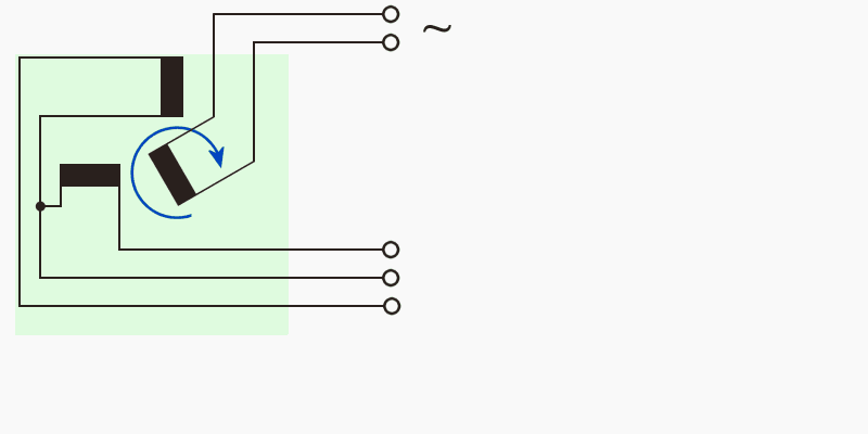
Figure 4: Resolver
Other applications need resolvers with two right-angle components (e.g. the deflection coils of a PPI-scope). Physically, resolvers are similar to synchros, and are used to perform mathematical computations electrically:
They are rotary electromechanical devices that provide outputs that are trigonometric functions of their inputs. They are used extensively in analog computers, radar sets, direction, and target designation equipment.