“Branch- Duplexer”
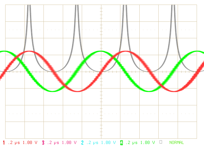
Figure 1: Current and voltage curves on a line

Figure 1: Current and voltage curves on a line
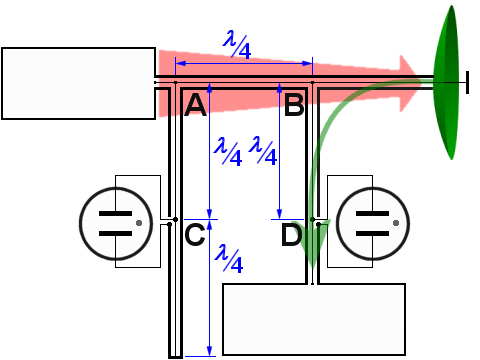
Figure 2: duplexer with quarter-wave co-axial stubs using TR- and ATR- Tube
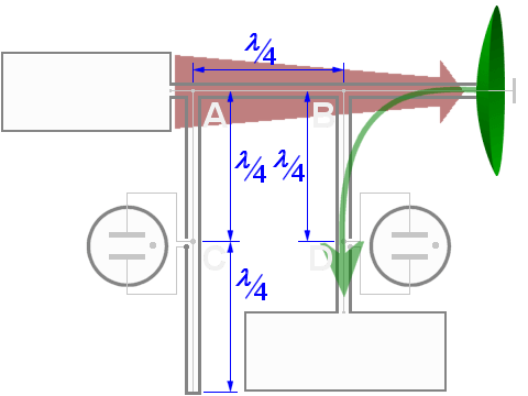
Figure 2: duplexer with quarter-wave co-axial stubs using TR- and ATR- Tube
The “Branch duplexer” is a transmit-receive switch, which consists of matched line segments. These matched line segments are short-circuited by gas discharge tubes or pin diodes, and conduct the high-frequency energy to the desired radar devices.
Preconditions
Important feature of the λ/4- line sections is the resistance transformation. Upon consideration of the voltage and current conditions on a line segment can be observed that in the line section:
- the current and voltage maxima occur at different times;
- at a maximum of the current there is a minimum voltage;
- if the current is zero there is a maximum voltage.
A current maximum occurs when a line is short-circuited. The short circuit means that at this point no voltage is measured – that is, the voltage has a minimum. A voltage maximum means that at this point are conditions as they exist in an open line: no current flows.
At a high frequency voltage maxima and minima alternate according to a sine function. The voltage is ahead the current by 90 degrees (equivalent to a quarter of the wavelength λ). The current maximum and the voltage maximum have on the line a distance of λ/4. If the resistance considered, then the formula R = V / I at one point with a maximum voltage (equivalent to current minimum) there is an infinitely high resistance. At a minimum voltage (and hence a current maximum), the resistance is zero. Due to the periodicity of the sine function a short circuit (resistance is zero) will be transformed after a distance of λ/4 to an infinite resistance, like at an “open line”. Furthermore, away λ/4, a short circuit could be measured again.
Principle of operation
A half-wavelength, closed-end section of transmission line, called a “stub”, is shunted across the main transmission line. An atr tube is located in this line one-quarter wavelength from the main transmission line and one-quarter wavelength from the closed end of the stub.
During the transmitting pulse, an arc appears across both the tr tube (at the point D) and the atr tube (at the point C) and causes the tr and atr circuits to act as shorted (closed-end) quarter-wave stubs. The circuits then reflect an open circuit to the tr (at the point B) and atr (at the point A) circuit connections to the main transmission line. None of the transmitted energy can pass through these reflected opens into the atr stub or into the receiver. Therefore, all of the transmitted energy is directed to the antenna.
Disadvantages of this kind of duplexer are:
- the frequency bandwidth is 5 per cent only;
- the power of the transmitter is limited
- the decoupling is lower than at other duplexers between transmitter and receiver
The resistance of a fired tr tube isn't zero, however. A single tr tube obtains an attenuation factor up to 30 dB only. Therefore several tr tubes are mounted on the connection to the receiver behind each other in a distances of λ/2 often.
During reception the amplitude of the received echo is not sufficient to cause an arc across either tube. Under this condition, the atr circuit now acts as a half-wave transmission line terminated in a short-circuit. This is reflected as an open circuit at the receiver T-junction (at the point B), three-quarter wavelengths away. The received echo sees an open circuit in the direction of the transmitter. However, the receiver input impedance is matched to the transmission line impedance so that the entire received signal will go to the receiver with a minimum amount of loss.
TR-Tubes
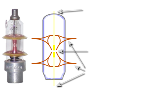
Figure 3: ATR-tube for waveguide stubs with a keep-alive electrode
Tr tubes are usually conventional spark gaps enclosed in partially evacuated, sealed glass envelopes, as shown in figure 2. The arc is formed as electrons are conducted through the ionized gas or vapor. You may lower the magnitude of voltage necessary to break down a gap by reducing the pressure of the gas that surrounds the electrodes. Optimum pressure achieves the most efficient tr operation. You can reduce the recovery time, or deionization time, of the gap by introducing water vapor into the tr tube. A tr tube containing water vapor at a pressure of 1 millimeter of mercury will recover in 0.5 microseconds. It is important for a tr tube to have a short recovery time to reduce the range at which targets near the radar can be detected. If, for example, echo signals reflected from nearby objects return to the radar before the tr tube has recovered, those signals will be unable to enter the receiver.
You may increase the speed with which the gap breaks down after the transmitter fires by placing a voltage across the gap electrodes. This potential is known as Keep-Alive Voltage and ranges from 100 volts to 1,000 volts. A glow discharge is maintained between the electrodes. (The term GLOW DISCHARGE refers to the discharge of electricity through a gas-filled electron tube. This is distinguished by a cathode glow and voltage drop much higher than the gas-ionization voltage in the cathode vicinity.) This action provides for rapid ionization when the transmitter pulse arrives.
TR tube as waveguide section
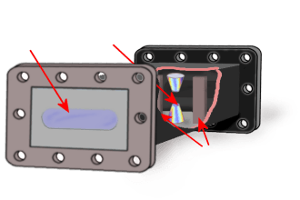
Figure 4: TR tube as a waveguide section
This tr tube used at microwave frequencies is built to fit into, and become a part of, a waveguide. The transmitted pulse travels up the guide and moves into the tr tube through a slot. During the transmitting pulse, an arc appears into the tr tube. One-quarter wavelength away, this action effectively closes the entrance to the receiver and limits the amount of energy entering the receiver to a small value. The windows of Quartz-glass (irises) are used to introduce an equivalent parallel-LC circuit across the waveguide for impedance matching.
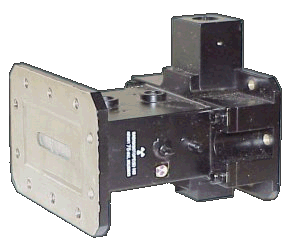
Figure 5: E.g.: TR-tube MD 80 S 2 of “Raytheon” Company.
This tr tube is a part of the tr-atr duplexer in the waveguide system of the
ASR-910.

The letters and the small sticker warns, this tr tube contains radioactive H3 (Tritium) gas. Handle with care to avoid breakage and possible contamination (0.6 to 1.3 Giga-Becquerels).
ATR-Tube
The atr tube is usually a simpler device than a tr tube. An atr tube might use a pure inert gas, such as argon, because recovery time generally is not a vital factor. Furthermore, a priming agent, such as keep-alive voltage, is not needed. The absence of either a chemically active gas or a keep-alive voltage results in atr tubes having longer useful lives than tr tubes.
The tr tube has the primary function of disconnecting the receiver, and the atr tube of disconnecting the transmitter.
