What is balanced duplexer?
“Balanced Duplexer”
The “Balanced Duplexer” is a duplexer designed for broadband radar systems with waveguide connection to the antenna. This duplexer has a very wide bandwidth, which is only limited by the cutoff frequencies of the waveguide. Radar sets operating with a plurality of requencies (frequency diversity and/or frequency agility) require such wideband systems.
Duplexers operating with λ/4 line stubs, such as the “Branch- Duplexer”, have only a very small bandwidth (less than 10 percent) because of exactly this frequency dependency (line lengths should be a quarter of the wavelength in the cable). Basically, they have only one working frequency! This limitation is unfavorable for reasons of jamming immunity.
Mode of Operation

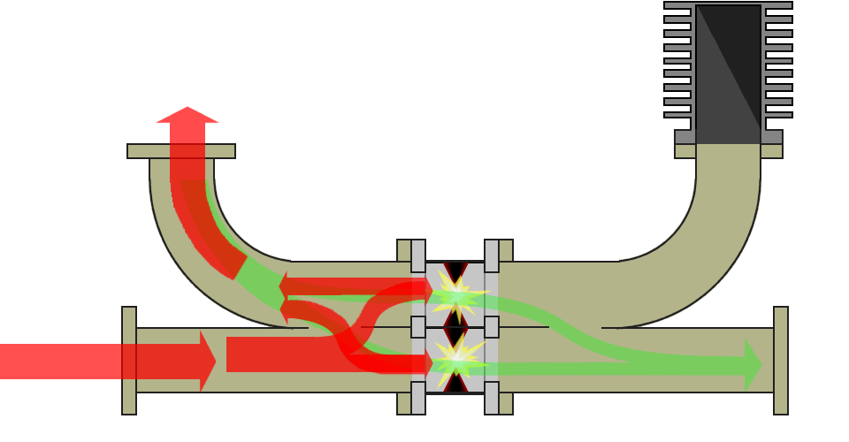
Figure 1: Principle of a “Balanced Duplexer” using -3 dB/90° Hybrids

Figure 1: Principle of a “Balanced Duplexer” using -3 dB/90° Hybrids
Mode of Operation
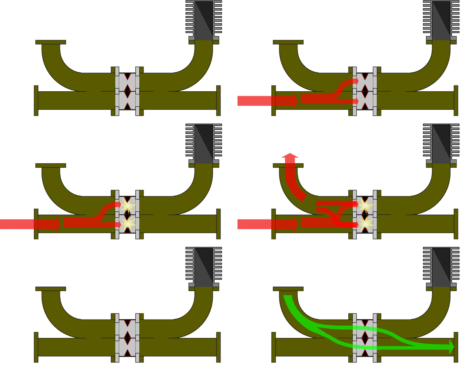
The "Balanced Duplexer" operates with -3db/90° - hybrid couplers according to the following sequence:
- A -3 dB-hybride divides the transmitters power in two parts;
- this part passed the slot of the hybride take a phase-shift of 90°;
- both parts of power cause an arc across both spark gaps
- these arcs short-circuit the waveguide and the power would be reflected;
- the power divides in the -3 dB-hybride once again;
- this part passed the slot of the hybride again take a phase-shift of 90°;
- among the parts in the direction of the transmitter occurs a phase-difference of 180° and for these both parts there is destructive interference;
- both parts in the direction of the antenna have the same phase and for these both parts there is constructive interference, i.e they accumulate to the full power.
During reception the amplitude of the received echo is not sufficient to cause an arc across either spark gap. both parts of the received echo can pass the spark gaps. The echoes recur both hybrides and accumulate their parts in-phase. The loss of this duplexer is about 0.5 … 1.5 dB.
What is the purpose of the dummy at the duplexer?
Dummy Load
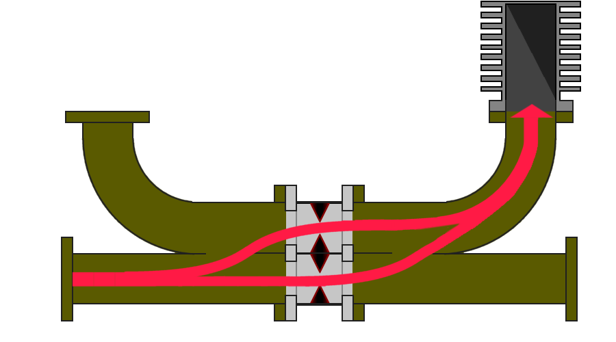
If the spark gaps have not ignited, the entire transmission power takes the path to the dummy load. There are several reasons for this unwanted cause:

Figure 2: Unwanted path of power when gas discharge tubes not ignite.
- Because the gas discharge tubes do not ignite immediately - they are quite inert and require, depending on the type, for example 10 nanoseconds, before their internal resistance assumes a value which brings about an almost complete reflection. At a transmitters pulse length of 1 μs, these 10 ns correspond to approximately 1 percent of the total pulse power.
- The gas discharge tubes cannot provide 100 percent protection. If they ignite, then their internal resistance is not equal to zero but still has values in the range of fractions of 1 Ω. There is therefore a proportion which is nevertheless passed but which is attenuated for example by approximately 50 to 60 dB.[1] At pulse power of 1 megawatts, this part would still be at least 1 to 10 watts.
- Gas discharge tubes require a minimum power to ignite. This minimum power can be, for example, 1 kW[1]. Now, however, the transmitters pulse does not have a precisely vertical rising edge. Some time elapses before the power has reached a value above 1 kW. Thus, before this power necessary for ignition is reached, this energy ends in the dummy load.
This dummy load must be relatively large, even if many of these power components are effective only for a very short time. In the worst case, it must withstand the continuous load of almost 1 kW (ignition power of the gas discharge tubes). In normal operation, the dummy should be only slightly but noticeably warm, due to these leakage currents.
Source:
- Datea sheet of the spark gap 6596 of Thomson CSF

