Duplexer with PIN- diodes

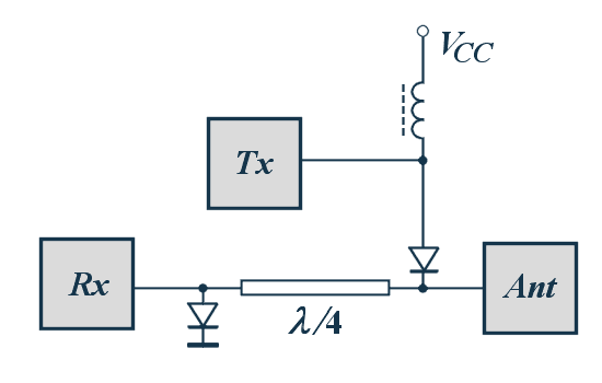
Figure 1: Principle of a duplexer with PIN- diodes

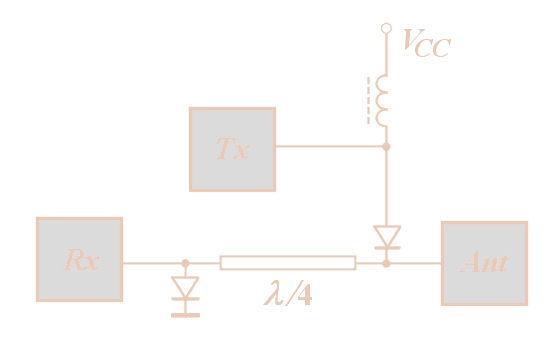
Figure 1: Principle of a duplexer with PIN- diodes
A PIN diode changes its internal resistance depending on the applied external voltage. This voltage is called bias. When the bias on a pin diode is varied, the microwave resistance changes from a typical value of 6 kilo-ohms under negative bias to about 5 ohms when the bias is positive. The PIN diode can be used as en electronically switch as shown in Figure 1.
- Case 1: The bias (Vcc) is positive.
both PIN diodes have got a very low resistance. The Power from the transmitter can pass the upper PIN- diode to the antenna. The lower PIN-diode has got a low resistance too and will be realize a short circuit to save the receivers input. But this low resistance will be transformed after the matched line with the length of λ/4 to a high value. The RF energy from the transmitter “sees” an open line here and will be led to the other direction, to the antenna with matched impedance. - Case 2: The bias (Vcc) is negative.
Both PIN diodes have got a higher resistance. The path to the transmitter is a nearly open line and the received power cannot travel to the transmitter. The PIN diode in the path to the receiver has a high resistance and a low affect of the traveling wave.
Fully solid-state duplexers based on PIN diodes are becoming an attractive alternative in the context of good isolation, fast recovery time and long life. A diode limiter passes low power signals with negligible attenuation but above a given threshold it attenuates the signal to a constant level. However, in high power environments, the devices have to be actively switched in order to achieve low loss and good isolation. This complicates the design and leads to increased risks of the catastrophic failure of the receiver if the duplexer drive circuits fail. Also high power handling capability comes at the price of reduced isolation and longer recovery times. More than one set of limiters is often used to achieve the required level of isolation.
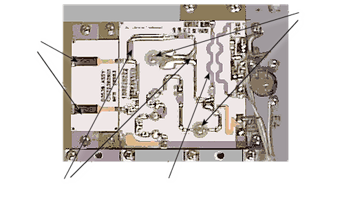
This module switches a short circuit with two PIN diodes in a line strip and switches therefore the RF-energie of the entrance into dependence of a control voltage either on the dummyloads or to the exit of this module (that means: to the receiver).

loads
diodes
Figure 2: duplexer with PIN- diodes in stripline technology

loads
diodes
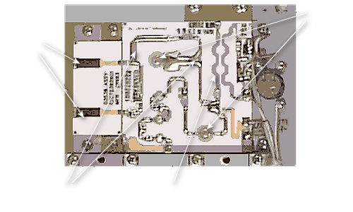
Figure 2: duplexer with PIN- diodes in stripline technology
Pin diodes need a control voltage which is usually provided by the synchronizer for switching.
|
Advantages: |
|
|
Disadvantages: |
|
