Yagi Antenna
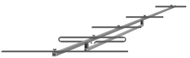
Figure 1: parts of a Yagi antenna
Figure 1: parts of a Yagi antenna
Yagi Antenna
Yagi antennas belong to the longitudinal radiators and use radiation-excited elements. It is named after one of its Japanese inventors, Professor Yagi, sometimes it is referred to as Yagi-Uda antenna. This antenna design has been specially developed for the range of radio waves from High frequency up to the upper UHF-band. Yagi antennas are very popular because of their simplicity and relatively high gain and are commonly referred to as high directive antennas. They are used also in radar sets, however.
Yagi antennas use mutual coupling between standing-wave current elements to produce a traveling-wave unidirectional pattern. It consists of an array of a dipole and additional closely coupled parasitic elements. The elements in the Yagi antenna are usually welded to a conducting rod or tube at their centers. This support does not interfere with the operation of the antenna. Since the driven element is center-fed, it is not welded to the supporting rod. The center impedance can be increased by using a folded dipole as the driven element.
The various elements are indicated in the figure. The spacings between the elements are not uniform. The only element of the structure that is excited is the dipole. All other parasitic elements are closely coupled with radiation. The radiation from the different elements arrives in phase in the forward direction, but out of phase by various amounts in the opposite directions. The bandwidth of a Yagi antenna is determined by the length, diameter, and spacing of the elements. For most designs bandwidth is typically only a few percents of the design frequency.
The Yagi antenna shown in Figure 1, has one reflector, one folded dipole as a radiator, and three directors. In general, the greater the number of parasitic elements (directors and reflectors) used, the greater the gain. However, a greater number of such elements causes the array to have a narrower frequency response as well as a narrower beamwidth. Therefore, proper adjustment of the antenna is critical. The gain does not increase directly with the number of elements used. For example, a three-element Yagi array has a relative power gain of 5 to 6 dB. Adding an additional director results in about 2 dB increase. But additional directors have less and less effect.
Principle of Operation
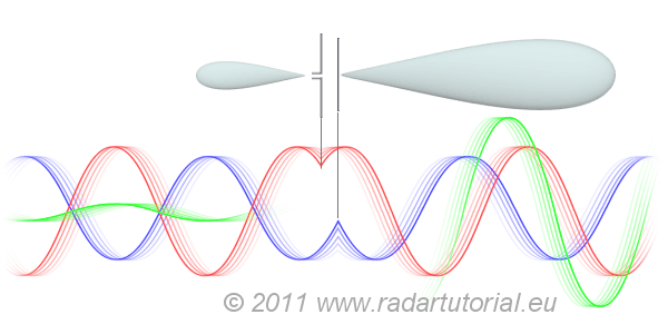
Figure 2: A two-element array of a half-wave resonant dipole as a driver and a shorter one as the parasite (snapshot of the traveling waves).
Figure 2: A two-element array of a half-wave resonant dipole as a driver and a shorter one as the parasite.
The basic unit of a Yagi consists of three elements. The length of every parasitic element differs from the resonant value of the half wavelength. If the length is longer (usually 15 percent), the element has got inductive characteristics and works as a reflector. If the length is shortening (in steps of 5 percent) the elements have got capacitive characteristics and are referred to as director since it appears to direct radiation in the direction from the driven dipole toward the director. For understanding the principle of operation we will begin with the resonant dipole and add a parasite element to the array close to the fed dipole. The exiting of the parasite element by radiating happens with a phase delay caused by the distance. The capacitive characteristic by the shorter length affects an additional delay of the currents and voltages in this element. If the phase delay corresponds with the distance of the elements, then both radiating fields are in-phase in one direction and out of phase in the other direction. Since the amplitudes of oscillation in both elements are not equal, the sum of both fields is increased in one direction and decreased in the other one.
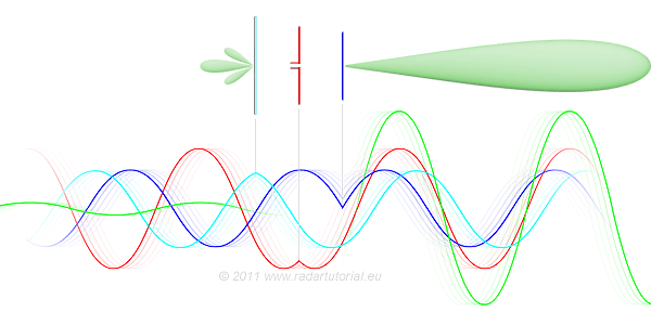
Figure 3: A 3–element-Yagi, superposition of the oscillations caused by the reflector, radiator, and director (snapshot of the traveling waves)
Figure 3: A 3–element-Yagi, superposition of the oscillations caused by the reflector, radiator, and director
The single end-fired beam created by using a driven dipole alone with a director suggests that even further enhancement could be achieved with a reflector and a director on opposite sides of the driven dipole. This is indeed the case. This three-element Yagi achieves an antenna gain up to 6 decibels. The longer reflector has an induced current in it that contributes a wave in the backward direction that just cancels the backward wave from the driven element. The director elements are slightly shorter, its self-impedance is capacitative and they have to be spaced closer than a half-wavelength in order to maintain equality of phase in the radiation contribution with the wave arriving from the radiator. The gain of a Yagi can be increased by increasing the number of elements but every additional element has got a less and less effect. For moderate numbers of elements, the forward gain is proportional to the number of elements.
The array of elements of the Yagi antenna can be described as a slow wave structure. The Yagi antenna is categorized to as Traveling-Wave Antenna, therefore. So the traveling wave structure supports a non-attenuating wave in the forward direction, and the currents in the directors are all approximately the same size, although with a progressive phase delay. This phase propagation speed is about 0.7 to 0.9 of the speed of light.
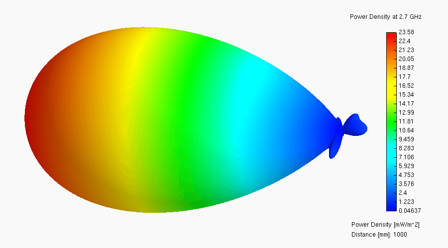
Figure 4: 3D representation of the antenna pattern of a Yagi antenna having 8 elements including folded dipole fed with a power of 11 dBm
Figure 4: 3D representation of the antenna pattern of a Yagi antenna having 8 elements including folded dipole fed with a power of 11 dBm
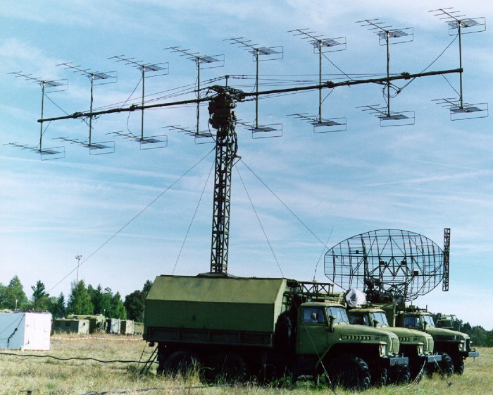
Figure 5: Radar using a group of Yagi antennas, (P-18 “Spoon Rest D”) antenna gain G = 69