Receivers Bandwidth

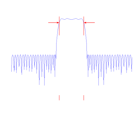
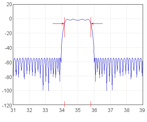
Figure 1: A graph of a bandpass filter's gain magnitude, illustrating the concept of -3 dB (or half-power) bandwidth

Figure 1: A graph of a bandpass filter's gain magnitude, illustrating the concept of -3 dB (or half-power) bandwidth

Figure 1: A graph of a bandpass filter's gain magnitude, illustrating the concept of -3 dB (or half-power) bandwidth
Receivers Bandwidth
Bandwidth
Bandwidth B, BW or Δf is the difference between the upper and lower cut-off frequencies of radar receiver, and is typically measured in hertz. In case of a baseband channel or video signal, the bandwidth is equal to its upper cut-off frequency. In a Radar receiver the bandwidth is mostly determined by the IF filter stages. The receiver must be able to process the signal bandwidth of the backscattered pulse.
The wider the bandwidth, the greater the degree of noise that will be input to the receiver. Since noise exists at all frequencies, the broader the frequency range to which the receiver bandpass filters are tuned, then the higher the intensity level of the noise and the lower the signal-to-noise ratio, and so the receivers sensibility.
The bandwidth is roughly proportional to the amount of information carried by the signal. To detect a rectangle pulse with the Fast Fourier Transformation (FFT) the bandwidth of the receiver is equal to the highest sine wave frequency component that is significant. The larger the bandwidth of the receiver, the shorter the rise time of the edges of the rectangular pulse.
Generally the necessary bandwidth B of a pulse in form of a half wave sine signal of duration τ is:
| B = | 1 | (1) |
| τ |
The influence of the Doppler effect will change the signal duration and bandwidth of the backscattered pulse. To obtain the Doppler information the installed bandwidth of the radar receiver must be higher than the signal bandwidth of the transmitted pulse.
In radar system using the intra-pulse modulation of the transmitted pulse, the necessary bandwidth of radar receiver is much higher than the reciprocal of their pulse width. In this case the necessary bandwidth of radar receiver depends on the internal modulation of the signal, the compressed pulse width and a weighting function, to achieve the required time sidelobe level. A maximum practical bandwidth of approximately 200 MHz is possible using current techniques. High-end receivers can have a tunable bandwidth.
Time Bandwidth Product
A common figure which characterises pulse compression devices is a time bandwidth product expressed as τ·B (in µs·MHz). Values of τ·B between 5 and 1000 can be achieved in some radar systems. For low values of τ·B, e.g. between 5 and 15, there are developed techniques which allow sidelobe suppression exceeding 35 dB, which is considerably better than expected. For τ·B between 15 and 500 as used in high end radar receivers, sidelobe levels can vary from 35dB to 45dB, depending on e.g the Doppler shift, mismatch loss trade-off, and the selected value of the Intermediate Frequency (IF).
A high Time Bandwidth Product of up to 1000 is usable for a high range resolution and an additional measuring of an altitude based on the time separation between the direct signal and the surface-reflected signal (Multipath Height Finding Method).
