Noise in Cascaded Amplifiers
F1
F2
F3
Fn-1
Fn
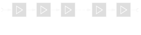
Figure 1: Noise in cascaded amplifiers
F1
F2
F3
Fn-1
Fn
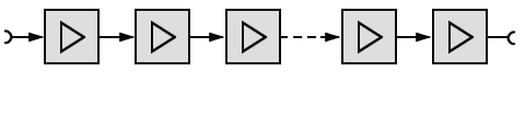
Figure 1: Noise in cascaded amplifiers
F1
F2
F3
Fn-1
Fn
Figure 1: Noise in cascaded amplifiers
The noise figure of a cascade of 2 components is given by:
where:
F represents the noise figure of the cascade,
F1 the noise figure of the first and
F2 the noise figure of the second component and
G1 the power gain of the first component.
The noise in this chain of amplifier circuits will be calculated with:
According to this equation: The first amplifier stage should have smallest noise and the last stage should have the smallest gain. Mixers are high noise components and the Low Noise Amplifier (LNA) plays a very important part in keeping the overall receiver noise level low.
All losses in front of the LNA must be kept to a minimum as they have a profound effect on the overall receiver noise figure. This is why the LNA is often mounted on the antenna, which minimises the “plumbing losses”.