Feed Horn
.png)
Figure 1: A self-made feed horn (soft soldered)
What ist a feed horn?
Feed Horn
A Horn or Feed Horn is a special antenna design for higher frequency ranges. The design more or less resembles the sound outlet of a brass-wind instrument, for example, a hunting horn. This funnel-shaped construction then ends into a waveguide. Horns are used both as a separate antenna or as a primary radiator to feed a reflector antenna (e.g. parabolic antenna). If it is used to feed a reflector antenna, it is called a feed horn.
Feed horns are widely used in microwave and millimeter wave bands because they provide moderate to high gain, low return loss, wide bandwidth and they are usually relatively easy to manufacture. The possible frequency range for this antenna design is limited only by the mechanical dimensions. It starts with feed horns for UHF-frequencies, and the upper boundary may be in W-Band.
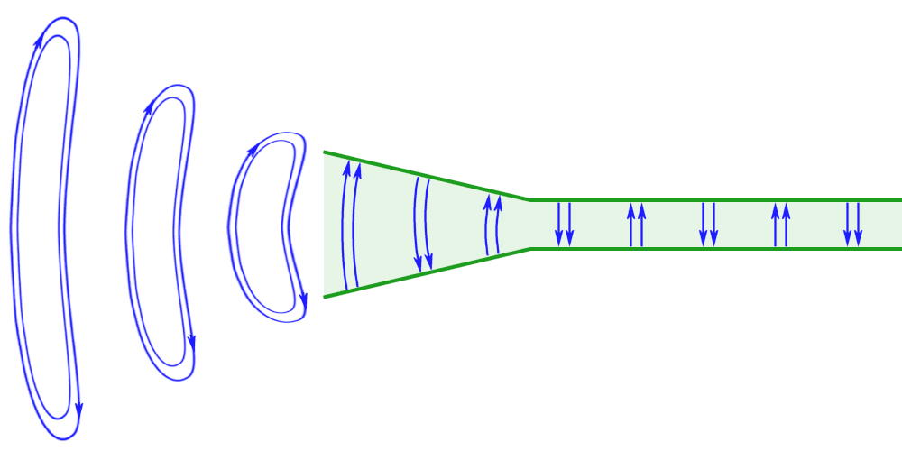
waveguide
Figure 2: Electric field lines in a waveguide; Transition from a conducted to radiated emission

waveguide
Figure 2: Electric field lines in a waveguide; Transition from a conducted to radiated emission

waveguide
emission
Figure 2: Electric field lines in a waveguide; Transition from a conducted to radiated emission
Function of a Horn
If the end of a waveguide is open, then only a part of the electromagnetic wave can be radiated. The waveguides characteristic impedance has got another value than the impedance of the free space (or air). This is a mismatch of the impedance, and in this case, a significant part of the power will be reflected.
The horn is essentially a flared waveguide. The flaring structure of the waveguide acts as an impedance transformer and matches the waveguide impedance to the free space impedance and therefore, enables the flared waveguide structure to radiate guided wave into free space. The horn is nothing more than a hollow pipe of different cross-sections which has been tapered to a larger opening. The type, direction, and amount of taper can have a profound effect on the overall performance of the element as a radiator. Horn antennas are typically fed by a section of a waveguide.
In most radars, the feed horn is covered with a window of polystyrene fiberglass to prevent moisture and dirt from entering the open end of the waveguide. If a dry-air pressure exists in the waveguide system, ceramic material or quartz glass is used as a covering material. However, this material is usually attached to the waveguide input connection of the feed horn. There you can better prevent reflections due to mismatching.
Characteristics
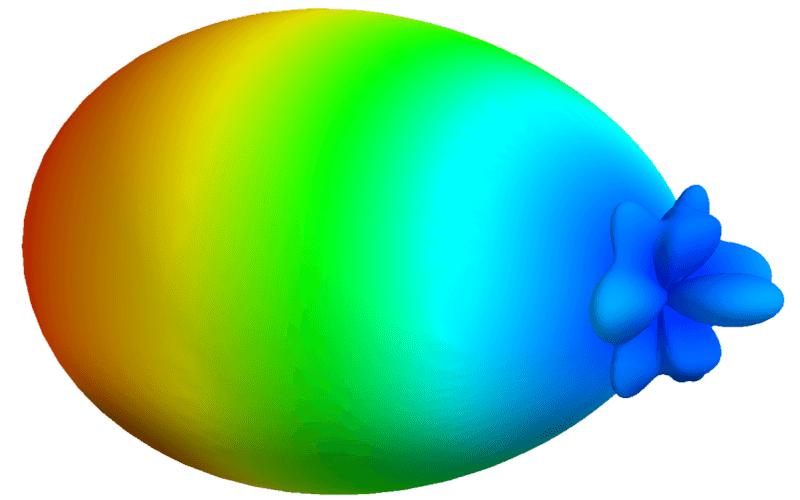
Horn antennas have a good directional characteristic, which depends on the design. A horn provides increased directivity if the aperture is large (i.e., the surface area of the flare) and the angle is low (i.e., the horn is long). The gain of a feed horn is proportional to its length times the aperture. Antenna gains of a horn are in the range around 20 to 23 dB. A respective doubling of the horn length causes an additional gain of 3 dB. At some point, the increased geometrical dimensions of the horn are very difficult to handle. Then it is better to install the horn in front of a focusing reflector. Horns have very little loss, so the directivity of a horn is roughly equal to its gain.
The directional characteristic and the antenna gain can be estimated with the following formula:
| D ≈ 10 log | 10 A | mit | A = area of the aperture λ = wave length [m] |
(1) |
| λ2 |
Types of horn antennas
In most radars, the feed horn is covered with a window of polystyrene fiberglass to prevent moisture and dirt from entering the open end of the waveguide. If a dry-air pressure exists in the waveguide system, ceramic materials or quartz glass is used as a covering material.
Pyramidal Horn
Theoretical basic forms of a horn would be the opening only in the E-plane and the opening only in the H-plane. (“E-plane or H-plane Sectoral Horn”) However, these basic forms are not often used in practice. Widely used is a horn, which flares in both the E-plane and the H-plane (see Figure 1). This kind of horn feed is called Pyramidal Horn. The degree of flaring can differ, resulting in asymmetric antenna diagrams. The bandwidth of this design is about half an octave.
Exponential Horn
An exponential horn radiator is a horn radiator whose cross-sectional area of the opening is described by an exponential function. This creates a smooth transition of the impedance of the value within the waveguide to the value in free space. Ideally, the reflection is very weak and the majority of the energy will be emitted.
Exponential horn radiators can have both a rectangular (pyramidal) or round (conical) basic shape.
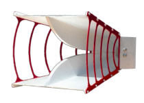
Ridged Horn
The ridged horn is a special design of a horn. In the middle of the upper and lower side “a” are exponentially opening metallic bars. Ridged horns operate over a large bandwidth of up to 3 octaves. The Vivaldi aerial is a planar variant of the ridged horn.
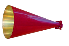
Conical Horn
A horn in the shape of a cone, with a circular cross-section. They are used with cylindrical waveguides. These are opened both in the E-plane and in the H-plane as the pyramidal horn.
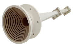
Corrugated Horn
A corrugated horn is a horn with parallel slots or grooves covering the inside surface of the horn. Corrugated horns have wider bandwidth and smaller sidelobes and cross-polarization Due to the inserted grooves with a depth of λ/4 the diagram symmetry and the polarization purity can be improved. The special features of this antenna are the low side lobes and the low internal losses. The bandwidth of this antenna is one octave. Due to the circular symmetry, these horn radiators can be used for all types of polarization.
Corrugated horns are widely used as feed horns for satellite dishes.
TEM Horn Antenna
Transverse electromagnetic (TEM) horn antenna is a special design of a horn. It consists of a combination of two metal surfaces approximated to the shape of an exponential funnel, which is electrically insulated from each other. The TEM horn antenna presents excellent characteristics in the field of UWB antennas. This form is mainly used as a very broadband test antenna for microwaves.
Picture gallery of hotm feeds
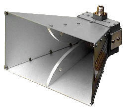
Figure 3: Double-ridged waveguide horn BBHA 9120 A of Schwarzbeck Mess-Elektronik
(data sheet)
bandwidth:800 MHz - 5 GHz
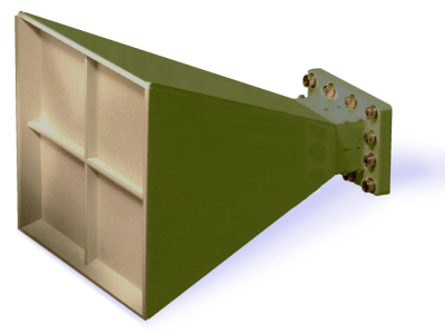
Figure 7: A so-called Monopulse Horn is a quadruple subdivided horn, in the common flange are continued four separate waveguides.
Further reading:
- Love, A. W. (Fd.): Electromagnetic horn antennas. New York: IEEE Antennas and Propagation Society 1976.
- Rudge. A.W.; Milne, K.; Olver. A.D.; Knight, P. (Eds.): The handbook of antenna design, Vol. I. London: Peter Peregrinus Ltd. 1982.
- Silver, S.: Microwave antenna theory and design. New York: McGraw-Hill 3949

