Standing Wave Ratio
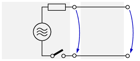
Figure 1: Replacement circuit diagram of a transmission line driven by a generator
Figure 1: Replacement circuit diagram of a transmission line driven by a generator
Standing Wave Ratio
Standing waves occur in transmission lines when they are used mismatched or maladjusted.
If a transmission line is terminated in its characteristic impedance then effect a maximum power transfer. A line cannot always be terminated in its characteristic impedance since it is sometimes operated as an
- open-ended line; and other times as a
- short-circuit at the receiving end.
If the line is open-ended, it has a terminating impedance that is infinitely large. If a line is not terminated in characteristic impedance, it is said to be finite.
When a line is not terminated in ZL, the incident energy is not absorbed but is returned along the only path available - the transmission line. Thus, the behavior of a finite line may be quite different from that of the infinite line.
Figure 2: Temporal sequence of the voltage on a transmission line
Figure 2: Temporal sequence of the voltage on a transmission line
Adjusted Inpedance
Before these special cases are examined has to be cleared what happens theoretically in one to long line infinitely, if an AC-Voltage is fed in. Termination shall be in its characteristic impedance (Ri = ZL).
Since Ri equals ZL, one-half the applied voltage will appear across the internal generator impedance, Ri, and one-half across the impedance of the line, ZL. The generator starts at the moment of switching on to send his power on the transmission line. At the time of t = 0 the voltage shall have her minimum value. This voltage value goes along the line with the spreading speed of the wave. This wave is called traveling wave.
If a transmission line is terminated in its characteristic impedance (ZL = Ra) then all power is transformed in heat inside the resistance Ra. The signal on this line behaves exactly as if it were infinitely long. The result is a traveling wave. It is characterized in that the signal is qualitatively measurable at each point of the transmission line.
Example given:A 5 m long transmission line (ZL= 75 Ω) is fed by a generator (Ri= 75 Ω) and it is terminated with a resistance of Ra= 75 Ω i.e. is there customization. The generator delivers an oscillation with a frequency of 30 Gigahertzes. How many oscillation antinodes are on this line?
Way of solving:
| λ = | c | = | 3·108 m/s | = 0,01 m |
| f | 3·1010 1/s |
| Number of oscillations = | Length of the transmission line | = | 5 m | = 500 oscillations |
| wave length | 0.01 m |
(Remember: contrary to this upper result using the speed of light, the wave length in a conductor differs from the wave length in free space!)
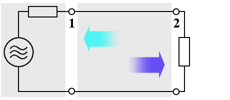
Figure 3: An un-customised transmission line
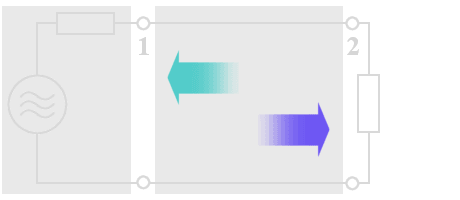
Figure 3: An un-customised transmission line
Mismatched Impedance
What happens with this wave, if there isn't a customization, while a load of e.g. 50 Ω (instead of 75 Ω) is in use?
The generator delivers the power Pgen. This power splits up after the following equation:
| PRi = PZL = ½ Pgen |
The power PZL = Pincident goes along the transmission line and reaches end terminator Ra. However, this one is smaller than at customization. Well, it cannot raise and change into warmth the complete power. A part of the power of PZL is left. This part is reflected and goes back to the generator as Preflected.
If ZL is dissimilarly Ra, a part of the to running wave is reflected always then. It is independently of this, whether Ra > ZL or Ra < ZL. In this case one speaks about maladjustment.
Interference
The following figure shows how two waves of the same frequency and amplitude moving in opposite directions on the same conductor will combine to form a resultant wave. The deep blue line is moving steadily from left to right and is the incident wave (from the source). The ice blue line waveform is moving from right to left and is the reflected wave. The resultant waveform, the red line, is found by algebraically adding instantaneous values of the two waveforms. The resultant waveform has an instantaneous peak amplitude that is equal to the sum of the peak amplitudes of the incident and reflected waves. Since most indicating instruments are unable to separate these voltages, they show the vector sum.
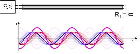
Figure 4: Risung of a standing wave
Figure 4: Risung of a standing wave
Whenever the termination is not equal to ZL, reflections occur on the line. For example, if the terminating element contains resistance, it absorbs some energy but if the resistive element does not equal the ZL of the line, some of the energy is reflected. The amount of voltage reflected may be found by using the equation:
| |r| = | Ureflected | = | |Ra-ZL| |
| Uincident | |Ra+ZL| |
| s = | Umax | = | Uincident · (1+r) | = | (1+r) |
| Umin | Uincident · (1-r) | (1-r) |
The ratio of maximum voltage to minimum voltage on a line is called the voltage standing-wave ratio (vswr). For higher frequencies the microwave-pover value is better measurable instead the voltage value. The ratio of the square of the maximum and minimum voltages is called the power standing-wave ratio (pswr). In a sense, the name is misleading because the power along a transmission line does not vary.