Skin-Effect

current I
through the
skin effect
decreases through
the skin effect
through the
skin effect
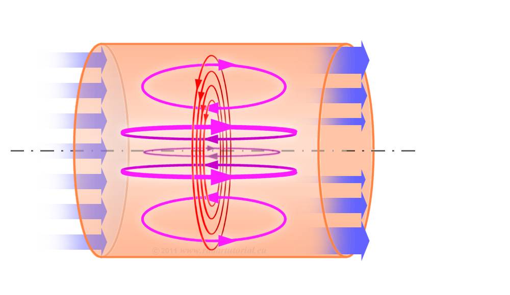
Figure 1: Visualisation of the skin effect

through the
skin effect
decreases through
the skin effect
through the
skin effect
Figure 1: Visualisation of the skin effect
Skin-Effect
At DC, current in a conductor flows with uniform density over the cross-section of the conductor. At radio frequencies, mobile charges within the material are made to oscillate back and forth with the same frequency as the impinging fields. These fields induce a current flowing in the opposite direction of the alternating current. The sum of both currents causes that the current flows only in a very thin “Skin”. Everywhere else the conductors are free from electromagnetic fields. Even very thin wallet metal envelopes will, therefore, entirely screen the electromagnetic field within coaxial RF cables at radio frequencies.
At high frequencies, the current tends to flow only in the conductor surface; the effective conductor cross-section decreases and the conductor resistance increases.
At high frequencies, the current tends to flow only in the conductor surface; the effective conductor cross-section decreases and the conductor resistance increases.
The depth of penetration illustrates the skin effect. It is defined as the thickness of a thin surface layer (assumed to have an even distribution of a current flow), having the same resistance as an actual conductor whitch is undergoing to skin effect.
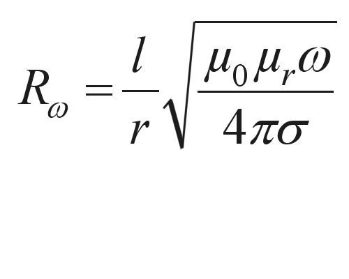
Because of the influence of the skin effect upon inductance the resistance is frequency-dependent:

 |
l cable length, |
