Monopulse Duplexer
Monopulse Duplexer
Tracking radar sets uses a monopulse antenna often. This antenna has got four equal feedhorns that are grouped in a cluster. The total amount of the energy received by each horn varies, depending on the position of the target relative to the beam axis. The monopulse system employs four such junctions to join the monopulse duplexer.
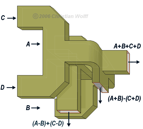
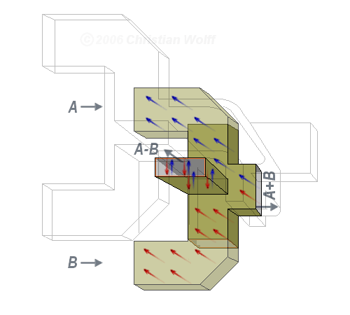
Wavefronts entering the four feedhorns (A, B, C and D) are illustrated in figure 1. Range is determined by the sum signal Σ which is the sum of all energy received by the four feedhorns. Assume that the monopulse duplexer receives horisontally polarized energy through the four feedhorns A, B, C, and D. The energy is shown in the expanded figure 2 by colored arrows. Various bending, adding and subtracting tricks are accomplished in the waveguide monopulse duplexer.
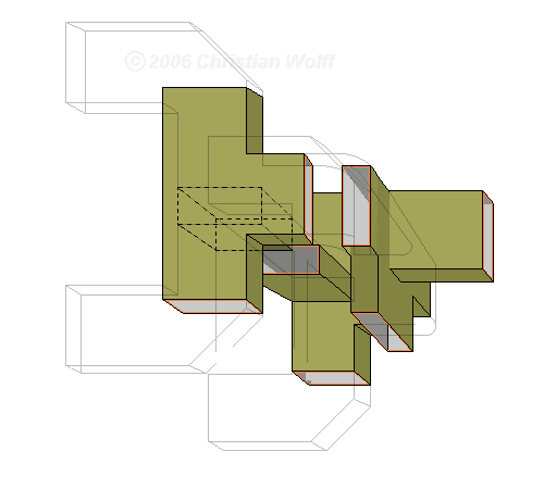
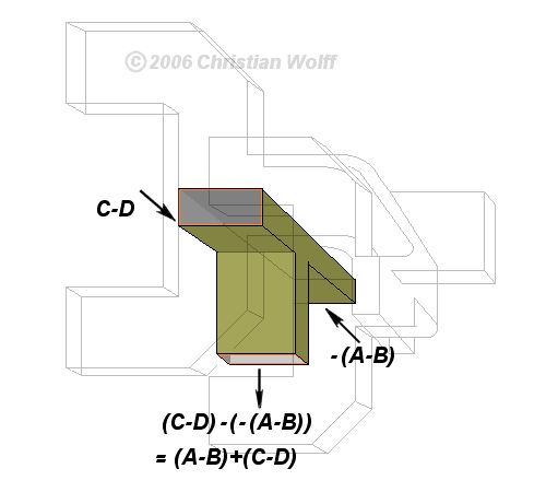
Figure 2 shows how a sum and a difference signal is obtained in a magic Tee hybrid. If the two entering wavefronts are of equal magnitude and of the same polarity, upon reaching the E–arm they will completely cancel each other and no output will result. If the two entering wavefronts are of different magnitudes but of the same polarity, their magnitude difference will appear in the E–arm. The resulting energy output for azimuth difference (ΔAz ) is (A+B)-(C+D) or the difference in energy level between the right two feedhorns and the left two feedhorns. The resulting energy output for elevation difference (ΔEl ) is (A-B)+(C-D) or the difference in energy between the top two feedhorns and the bottom two feedhorns.
A total of three magic Tees are used. The resulting outputs of these tree magic Tees are:
- generation of the signals A-B and A+B;
- generation of the signals C-D and C+D; and
- generation of the signals ΔEl = (A+B)-(C+D) and Σ = A+B+C+D
An onward E-type T-junction obtains the signal ΔAz = (A-B)+(C-D)
The difference signals, azimuth and elevation, are processed to move the antenna so that it is always pointing at the target.

