Velocity-modulated Tubes

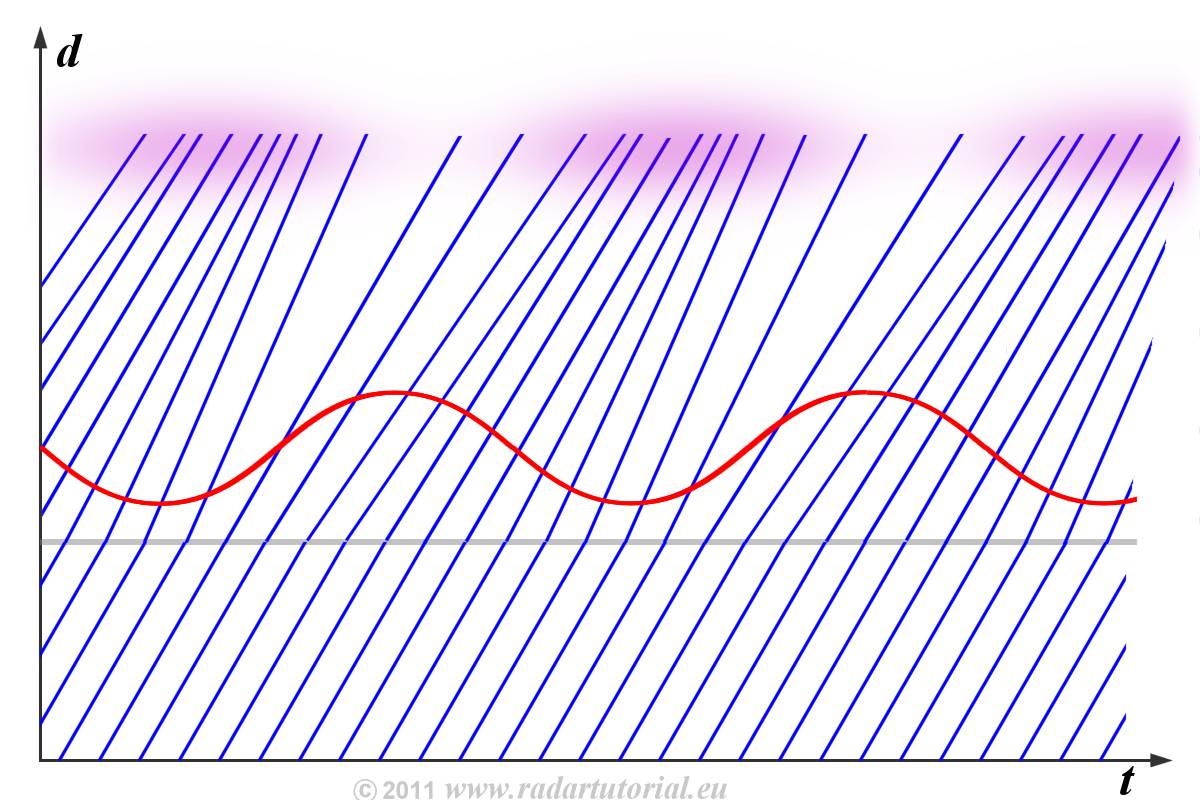
Figure 1: Formation of electron bunches by velocity modulation

Figure 1: Formation of electron bunches by velocity modulation

by the static anode voltage
of the resonator
Figure 1: Formation of electron bunches by velocity modulation
Velocity-modulated Tubes
The microwave tube uses transit time in the conversion of dc power to radio-frequency power. The interchange of power is accomplished by using the principle of electron velocity modulation and low-loss resonant cavities in the microwave tube.
Velocity modulation is then defined as that variation in the velocity of a beam of electrons
caused by the alternate speeding up and slowing down of the electrons in the beam. This variation
is usually caused by a voltage signal applied between the grids through which the beam must pass.
Acceleration of electrons by the static anode voltage:
By the anode voltage, the electrons are accelerated uniformly.
These get at all times a constant speed of v=d/t.
This is shown in the diagram as a uniform slope angle in the bottom region.
Influence of the RF voltage of the resonator:
An input resonator is externally excited by a high-frequency oscillation.
Through this oscillation, the electrons are either in addition to accelerated or decelerated (during the positive half-wave)
or decelerated (negative half-wave). The faster electrons overtake the slower electrons in the drift space.
Formation of electron bunches:
Due to the different velocity electron bunches are formed.
The electrons were given a large energy due to the high anode voltage.
An output resonator is excited by the electron bunches to a powerful oscillation in the frequency of the input oscillation.
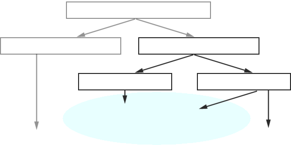
The direction of the electron beam and the static electrical field goes to each other parallelly
(linearly) into linear beam tubes. Against this the fields influencing the electron beam stand
vertically by the electron beam at the cross field tubes.

field is required
Magnetron
Stabilotron
Carcinotron
EIK/EIO

field is required
The following table compares with characteristic quantities of the velocity-modulated tubes used in radar technology. Although the planar tube isn't a velocity-modulated tube, it was included into this table for comparison purposes.
| Klystron | Traveling Wave Tube | EIK/EIO | Magnetron | Carcinotron | planar tube | |
| frequency | up to 35 GHz | up to 95 GHz | up to 230 GHz | up to 95 GHz | up to 5 GHz | up to 1.5 GHz |
| bandwidth | 2 - 4 % | 10 - 20 % | 0,5 - 1 % | a few Megahertz | 2 GHz | 30 - 50% |
| power output | up to 50 MW | up to 1 MW | up to 1 kW | up to 10 MW | 1 W | up to 1 MW |
| amplification | up to 60 dB | up to 50 dB | 40 - 50 dB | - | - | up to 20 dB |
| function as | small-band power amplifier | wide-band, lownoise voltage amplifier | small-band power amplifier and generator | high power oscillator at one frequency | frequency-controlled oscillator (VFO) | amplifier, oscillator |
Table 1: Comparing of velocity-modulated tubes
